Lafferty Equipment Manufacturing, LLC

Installation & Operation Instructions

Model # 932607-V · 2-Way APV MM Concrete Sprayer

Requirements

Chemical Concentrate
Static Tank of Water
Compressed Air up to 4 CFM
Hose 1/2" ID x 50'
Nozzle 2520

Options

Stainless Steel Hose Racks
Large Stainless Steel Hose Rack# 224150
Stainless Steel Jug Racks
2 ½ Gal. (8 ½'' x 10 ½'') # 224210
5 Gallon (12" x 12") Round/Square# 224215
Drum & Tote Stick Lengths & Seal Materials
Drum Stick, 33" (Viton or EPDM)# 491643 / 491643-E
Drum Stick, 48" (Viton or EPDM)# 491648 / 491648-E
Drum Stick, 54" (Viton or EPDM)# 491645 / 491645-E
Tote Stick, 33" (Viton or EPDM)# 491653 / 491653-E
Tote Stick, 48" (Viton or EPDM)# 491654 / 491654-E
Tote Stick, 54" (Viton or EPDM)# 491656 / 491656-E
932607-V
PVC_wand_BLACK_noz-protect.jpg
Warning! Read All Instructions Before Using Equipment!

Overview

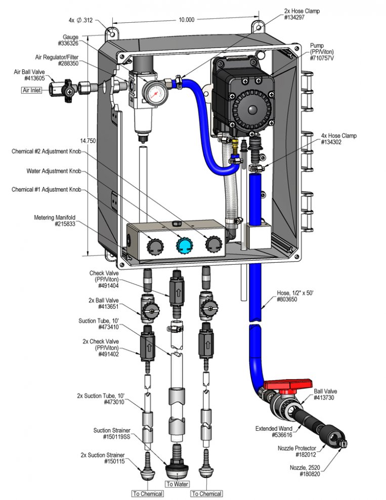
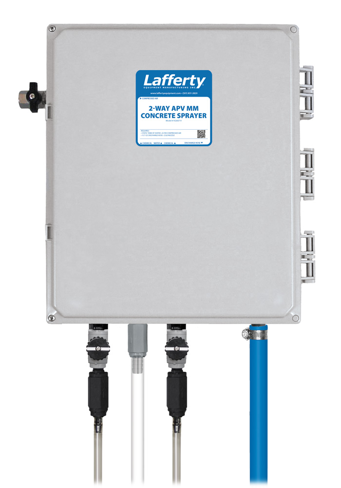
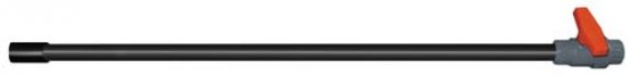
The 2-Way APV MM Concrete Sprayer is a spray applicator for projecting 2 highly corrosive chemicals such as those used to remove concrete and for aluminum brightening. It is designed for facilities with low or no water pressure. This acid-resistant system uses an air-operated, double-diaphragm, Flojet pump to draw water and chemical concentrate from separate static tanks and blend them to create a wide range of dilution ratios. A uniform spray is then projected through the hose, wand and fan nozzle on to any surface. Alternate between 2 different concentrations or chemicals using ball valves.

Safety & Operational Precautions

  • For proper performance do NOT modify, substitute nozzle, hose diameter or length
  • Manufacturer assumes no liability for the use or misuse of this unit.
  • Wear protective clothing, gloves and eye-wear when working with chemicals.
  • Always direct the discharge away from people and electrical devices.
  • Follow the chemical manufacturer’s safe handling instructions.
  • DO NOT use chemicals that are not compatible with Viton diaphragms.

To Install (refer to diagram on next page)

  1. Mount the unit above chemical and / or water containers.
  2. Securely attach the suction tubes to the check valves as shown in the drawing.
  3. Place one tube/strainer in the chemical concentrate(s) and the other in a static container of water. (DO NOT use pressurized water!)
  4. Attach a compressed airline to the inlet ball valve. DO NOT TURN ON
How to Set Your Dilution Ratio:
  • The adjustment knobs allow you to achieve wide range of dilution ratios.
  • Turn adjustment knobs counterclockwise to increase flow or clockwise to decrease flow.
  • For a starting place turn the water knob completely clockwise (closed) then turn 2 turns counterclockwise (open).
  • Then turn the chemical knob completely clockwise (closed) then counterclockwise (open) in 1/4 to 1/2 turn increments until required dilution ratios are achieved.
  • If ratios can't be achieved with the chemical knob all the way counterclockwise start turning water knob clockwise to shift more draw to the chemical side.

To Operate

Always make sure the discharge is closed or pointed in a safe direction before turning inlet valve on. Discharge can be shut off at any time during operation but should not be left off for long periods of time with the inlet valve on.

  1. Open the air ball valve and one chemical ball valve, point wand in a safe direction and completely open the ball valve. Make final chemical dilution adjustments to the metering manifold based on cleaning results.
  2. Close the ball valve when finished, return to the unit then close chemical ball valve if you are finished applying chemical close the air ball valve and release pressure in hose.
  3. If a 2nd chemical will be applied repeat step 1 & 2.
  4. When application is completed, close the discharge ball valve, return to the unit and close the chemical ball valves and the air ball valve . Briefly re-open the discharge ball valve to relieve pressure in  the hose
  5. Rinse the surface before the spray dries to avoid reapplication.

Unit Flow Rates

PSIGPM
602.00
932607-V.jpg
Troubleshooting Guide
Problem Possible Cause / Solution
StartupMaintenance
A) Air pump will not run or pump solution.
B) Unit will not draw chemical or water.
C) Using too much chemical
D) Chemical not effective.
E) Pump runs too fast with no output.

1,2,6
3,6
4
5
7,12,13
8,9,10,11,12


8,9,10,11,12
Possible Cause / Solution
StartupMaintenance
  1. Air adjustment too low
    • Open air ball valve fully. Adjust air regulator slowly clockwise. Optimum air pressure is 60 PSI.
       
  2. Ice particles from condensation in air line — Air pump can periodically "freeze up" (stall) due to ice particles in the pump's exhaust (depending on air humidity etc.)
    • WAIT several seconds to allow the ice particles to melt and blow out, at which time the pump will automatically resume  pumping.
  3. Water or chemical tube not immersed in container or container empty
    • Immerse tube or replenish.
  4. Dilution too strong
    • Turn chemical knob slightly clockwise or water knob counterclockwise.
  5. Dilution too weak
    • Turn chemical knob slightly counterclockwise or water knob clockwise.
  6. Discharge hose kinked
    •   Straighten the hose.
  1. Air regulator clogged or failed
    • Clean or replace.
  2. Water or chemical check valve stuck or clogged
    • Clean or replace.
  3. Chemical or water strainer clogged up
    • Clean or replace.
  4. Vacuum leak in metering manifold
    • Tighten the connection(s).
  5. Chemical or water tube stretched out where tube slides over check valves or pin hole/cut in tube sucking air.
    •   Cut off end of tube or replace tube.
  6. Problem with air pump
  7. Use of an oiler in the airline will cause pump to stall
    • Use only clean, dry air.
PREVENTIVE MAINTENANCE: When the unit will be out of service for extended periods, place chemical tube(s) in water and flush the chemical out of the unit to help prevent chemical from drying out and causing build-up. Periodically check and clean chemical strainer and replace if missing.