Lafferty Equipment Manufacturing, LLC

Installation & Operation Instructions

Model # 977895 · Magnetic EP-LM Asphalt Release Spray System

Requirements

Chemical Concentrate
Water
Temperature up to 160°F
Pressure 35 to 125 PSI
Supply Line 1/2"
Hose 3/4" ID x 40'
Nozzle #180193SS
Electric 120V
See Separate Instructions for:
Level Master™ 989304

Options

Heater Assembly
Retro-Fit Heater Assembly# 720981
Drum & Tote Stick Lengths & Seal Materials
Drum Stick, 33" (Viton or EPDM)# 491643 / 491643-E
Drum Stick, 48" (Viton or EPDM)# 491648 / 491648-E
Drum Stick, 54" (Viton or EPDM)# 491645 / 491645-E
Tote Stick, 33" (Viton or EPDM)# 491653 / 491653-E
Tote Stick, 48" (Viton or EPDM)# 491654 / 491654-E
Tote Stick, 54" (Viton or EPDM)# 491656 / 491656-E
Level Masters Provide an Automatic Supply
of Ready-to-Use Chemical
Level Master (Various Tank Sizes)# 989304
Gemini Level Master (Various Tank Sizes)# 989316
977895
Warning! Read All Instructions Before Using Equipment!

Overview

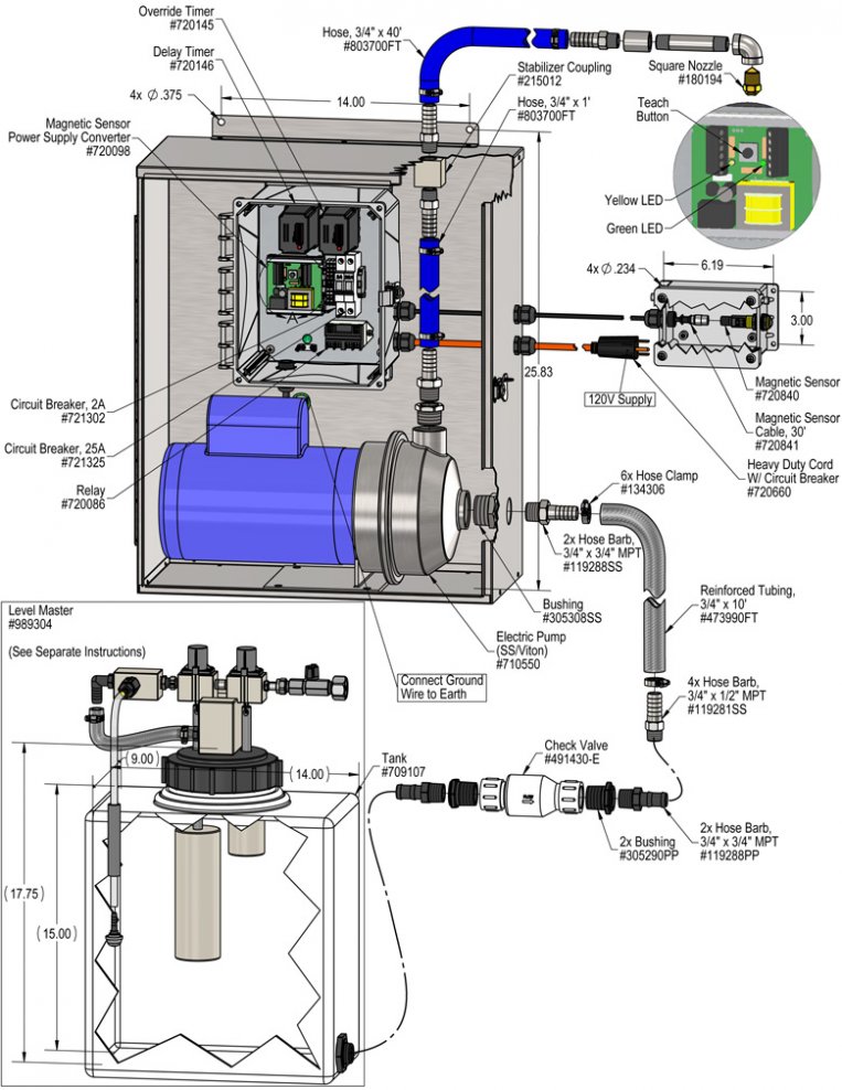
The Magnetic EP-LM Asphalt Release Spray System is a magnetic sensor activated, time delayed, asphalt release applicator that mounts to a user-supplied drive-though arch for spraying asphalt truck beds. This system uses an electric pump to draw ready-to-use chemical from the included Level Masterâ„¢ tank which maintains a constant supply of solution. When a truck comes into range of the magnetic sensor, a delay timer allows the driver to position the truck under the spray nozzle before spraying begins and a run timer applies release agent for a pre-set time or until the vehicle leaves the spraying area, whichever is first.

Safety & Operational Precautions

  • See Additional Safety Instructions included with the Electrical Control Box
  • Always consider electrical shock hazard when working with and handling electrical equipment. If uncertain, consult an Electrician. Electrical wiring should only be done by a qualified Electrician per Local and State Electrical Codes.
  • For proper performance do NOT modify, substitute nozzle, hose diameter or length.
  • Manufacturer assumes no liability for the use or misuse of this unit.
  • Wear protective clothing, gloves and eye wear when working with chemicals.
  • Always direct the discharge away from people and electrical devices.
  • Follow the chemical manufacturer's safe handling instructions.
  • NEVER mix chemicals without first consulting chemical manufacturer.
  • Operate the electric pump according to the limitations specified on the data label.
  • Do not use with flammable or hazardous fluids not compatible with stainless steel. 

To Install (refer to diagram on next page)

  1. Mount the unit to a solid, secure surface within 15' of the drive lane. This is a centrifugal pump and will need primed the first time it is used and each time it runs dry. Mount close to and not higher than the Level Master, it needs to gravity feed to the pump.
  2. Do NOT connect to electricity yet.
  3. Construct the mounting arch, then mount the nozzle assembly as shown in the illustration on page 1. To prevent dripping after each cycle leave a loop in the hose to make the nozzle higher than the bottom of the loop.
  4. Mount Magnetic Sensor and perform set-up procedure. See separate Insert "Installation and Set-up Instructions for Magnetic Sensor".
  5. Connect the 3/4" suction tube to the hose barb. Secure all tubes with the clamps – do not over-tighten. Immerse suction tube into a container of water for initial testing.
  6. Make sure the system is not plugged in to a power source. Remove control box cover. The box contains two timers (Delay & Override).
    Delay Timer: This timer allows you to set the time to the approximate number of seconds needed from the time the truck triggers the magnetic sensor until the truck bed is positioned underneath the nozzles. Set the timer by pushing the combination of dip switches that will equal the total number of seconds you need for the delay.
    Override Timer: This timer controls the maximum amount of time the sprayer will operate for. Set the timer by pushing the combination of dip switches that equal the total number of seconds you need the system to spray. Note: if the truck exits before this time has elapsed, the spray will stop. (Note: Some later models contain an Override Timer with two dials. If this is the case, turn the bottom dial to zero and turn the top dial (marked Run) to the amount of time you want the sprayer to operate for - 0-6 minutes)
  7. Replace the control box cover.
  8. Plug power cord into 120 VAC outlet on dedicated 20A breaker.
TO TEST
  1. The pump may take a few seconds to prime, fill the suction tube with water to help the pump prime the first time.
  2. Perform "test runs" with water only and make any necessary timer adjustments, and any nozzle and magnetic sensor sensitivity adjustments.
  3. The system will shut off when the magnetic sensor no longer senses the truck. Make sure the sensitivity level is set so that any gap between the cab and the bed of the truck does not cause the system to shut off.
  4. After several successful test runs have been made you are ready to operate.
  5. Set up the Level Master and connect the suction tube to the Level Master.

To Operate

Once adjustments have been made to timers and chemical dilution:

  1. Drive the first truck through and make any last adjustments as needed.
  2. The unit is ready for operation.
977895.jpg
Troubleshooting Guide
Problem Possible Cause / Solution
StartupMaintenance
A) Pump will not run or pump.
B) Pump runs with no output.
C) Unit will not draw chemical.
D) Suction tube will not stay primed.
E) Unit comes on and runs continuously.
G) Asphalt continues to stick to truck.
1,2,3,4,5
2,3
2,3
7
4,5

6,7,8
6,7,8

8

6
Possible Cause / Solution
StartupMaintenance
  1. Problem with pump
    • Refer to pump manual.
  2. Suction hose not immersed or connected to chemical solution or depleted.
    • Immerse tube, tighten connection or replenish.
  3. Discharge hose kinked.
    • Straighten
  4. Timer not set properly or malfunctioned
    • See Timer Adjustment on page 2 or replace timer.
  5. May have electrical problems
    • Have a qualified electrician check electrical connections.
    • Ensure circuit breaker in control box has not been tripped.
    • Ensure main outlet breaker has not been tripped.  See requirements.
    • Make sure the sensor has not been moved or the surroundings have not changed
    • May have to re-teach the sensor.
  1. Chemical strainer blocked or chemical concentration too weak
    • Clean or replace chemical strainer.
    • Increase chemical concentration.
  2.   Vacuum leak in suction hose.
    • Tighten the clamps and check the barbs.
  3.   Check valve stuck or failed
    • Clean or replace.
PREVENTIVE MAINTENANCE: When the unit will be out of service for extended periods, place chemical tube(s) in water and flush the chemical out of the unit to help prevent chemical from drying out and causing build-up. Periodically check and clean chemical strainer and replace if missing.