Lafferty Equipment Manufacturing, LLC

Installation & Operation Instructions

Model # 931108WPS · WPS-MM Asphalt Release Sprayer

Requirements

Chemical Concentrate
Static Tank of Water
Compressed Air up to 4 CFM
Hose 1/2" ID x 25'
Nozzle 2520

Options

Stainless Steel Hose Racks
Large Stainless Steel Hose Rack# 224150
Stainless Steel Jug Racks
2 ½ Gal. (8 ½'' x 10 ½'') # 224210
5 Gallon (12" x 12") Round/Square# 224215
Drum & Tote Stick Lengths & Seal Materials
Drum Stick, 33" (Viton or EPDM)# 491643 / 491643-E
Drum Stick, 48" (Viton or EPDM)# 491648 / 491648-E
Drum Stick, 54" (Viton or EPDM)# 491645 / 491645-E
Tote Stick, 33" (Viton or EPDM)# 491653 / 491653-E
Tote Stick, 48" (Viton or EPDM)# 491654 / 491654-E
Tote Stick, 54" (Viton or EPDM)# 491656 / 491656-E
Poly/Teflon and Kynar/Teflon Air Pumps
(Poly/Santoprene Standard)
Pump, WR Poly/Teflon, 3/8", 7GPM Max# 710911
Pump, WR Kynar/Teflon, 3/8", 7GPM Max# 710912
931108WPS
Warning! Read All Instructions Before Using Equipment!

Overview

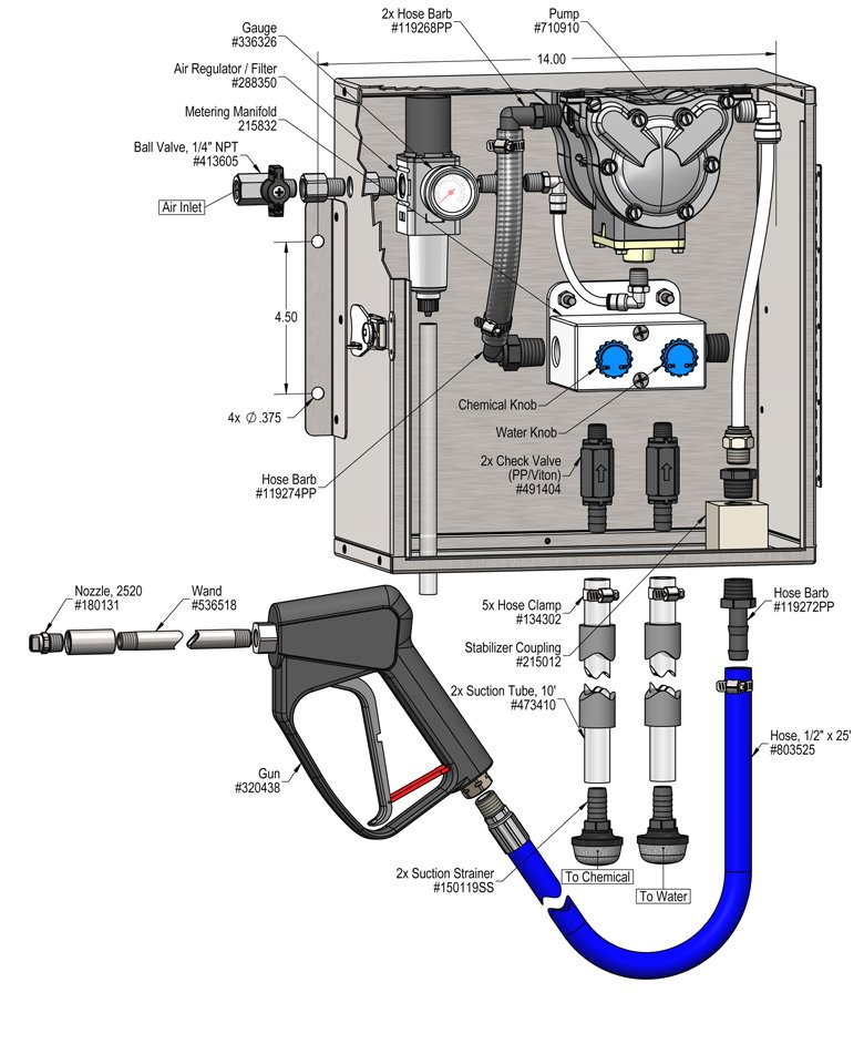
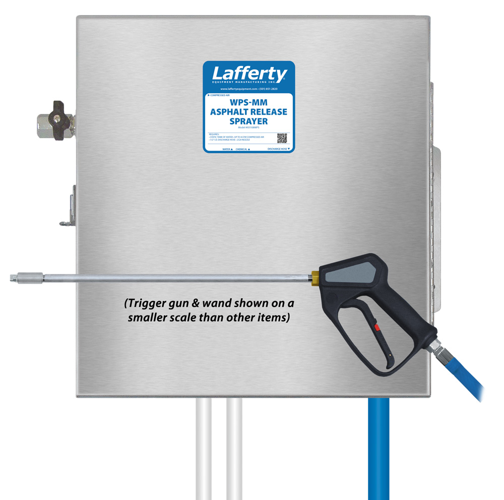
The WPS-MM Asphalt Release Sprayer is a chemical spray applicator for diluting and projecting asphalt release chemicals on to truck beds or tools to prevent asphalt from sticking. This system features a lockable, stainless steel enclosure and uses a 3/8" Warren Rupp air-operated, double-diaphragm pump to draw chemical concentrate and water from separate static tanks and blend them to create virtually any dilution ratio. The solution is then projected through the discharge hose, trigger gun, wand and fan nozzle.

Safety & Operational Precautions

  • For proper performance do NOT modify, substitute nozzle, hose diameter or length
  • Manufacturer assumes no liability for the use or misuse of this unit.
  • Wear protective clothing, gloves and eye-wear when working with chemicals.
  • Always direct the discharge away from people and electrical devices.
  • Follow the chemical manufacturer’s safe handling instructions.
  • DO NOT use d-Limonene or other chemicals that are not compatible with the Santoprene diaphragms.

To Install (refer to diagram on next page)

  1. Mount the unit above chemical and / or water containers.
  2. Securely attach the suction tubes to the check valves as shown in the drawing.
  3. Place one tube/strainer in the chemical concentrate(s) and the other in a static container of water. (DO NOT use pressurized water!)
  4. Attach a compressed airline to the inlet ball valve. DO NOT TURN ON
How to Set Your Dilution Ratio:
  • The adjustment knobs allow you to achieve wide range of dilution ratios.
  • Turn adjustment knobs counterclockwise to increase flow or clockwise to decrease flow.
  • For a starting place turn the water knob completely clockwise (closed) then turn 2 turns counterclockwise (open).
  • Then turn the chemical knob completely clockwise (closed) then counterclockwise (open) in 1/4 to 1/2 turn increments until required dilution ratios are achieved.
  • If ratios can't be achieved with the chemical knob all the way counterclockwise start turning water knob clockwise to shift more draw to the chemical side.

To Operate

Always make sure the discharge is pointed in a safe direction before turning inlet valve on. Trigger can be released at any time during operation but should not be left unattended for long periods of time without closing inlet ball valve.
  1. Open the inlet ball valve point the wand in a safe direction and pull the trigger on the gun.
  2. Final chemical dilution adjustments will now have to be made. Make adjustments to the knobs based on results.
  3. If the solution seems to be too weak slowly turn the chemical knob counterclockwise.
  4. Continue opening till the solution is strong enough for the application.
  5. Once dilution ratio is set, release the trigger gun or begin application.

Unit Flow Rates

PSIGPM
602.00
931108WPS.jpg
Troubleshooting Guide
Problem Possible Cause / Solution
StartupMaintenance
A) Air pump will not run or pump solution.
B) Unit will not draw chemical or water.
C) Using too much chemical
D) Asphalt sticking in truck bed.
E) Pump runs too fast with no output.

1,5
2,5
3
4
6,11,12
7, 8, 9,10,11


7,8,9,10,11
Possible Cause / Solution
StartupMaintenance
  1.  Air adjustment too low
    • Open air ball valve fully. Adjust air regulator slowly clockwise. Optimum air pressure is at least 60 PSI 90 PSI maximum.
  2. Water or chemical tube not immersed in container or container empty
    • Immerse tube or replenish.
  3. Dilution too strong
    • Turn chemical knob slightly clockwise or water knob counterclockwise.
  4. Dilution too weak
    • Turn chemical knob slightly counterclockwise or water knob clockwise.
  5. Discharge hose kinked
    • Straighten the hose.
  1. Air regulator clogged or failed
    • Clean or replace.
  2. Water or chemical check valve stuck or clogged
    • Clean or replace.
  3. Chemical or water strainer clogged up
    • Clean or replace.
  4. Vacuum leak in metering manifold or suction side of the pump
    • Check and tighten the hose clamps connection(s). After unit has been in service the plastic fittings could have "relaxed" and may need tightened too.
    • NOTE: This is the most common problem when the unit will not draw water or chemical!
  5. Chemical or water tube stretched out where tube slides over check valves or pin hole/cut in tube sucking air.
    • Cut off end of tube or replace tube, add a hose clamp, do not over tighten.
  6. Problem with air pump
    • Refer to air pump instruction manual.
    • Pump suction and discharge manifolds are loose, tighten bolts.
  7. Use of an oiler in the airline will cause pump to stall
    • Use only clean, dry air.
PREVENTIVE MAINTENANCE: When the unit will be out of service for extended periods, place chemical tube(s) in water and flush the chemical out of the unit to help prevent chemical from drying out and causing build-up. Periodically check and clean chemical strainer and replace if missing.