Lafferty Equipment Manufacturing, LLC

Installation & Operation Instructions

Model # 982150 · Gemini™ Model 150 Mixing Station

Requirements

Chemical Concentrate
Water
Temperature up to 160°F
Pressure 35 to 125 PSI
Flow 7 GPM @ 40 PSI
Supply Line 3/4"

Options

Stainless Steel Jug Racks
Jug Rack, SS, 1 Gallon, Round/Square# 224200
Jug Rack, SS, 2 1/2 Gallon# 224210
Jug Rack, SS, 5 Gallon, Round/Square# 224215
Safe Flow Lid™ for 1 Gallon Jugs
Lid, Suction Tube, and Strainer# 709101
Alternate Check Valves - Viton Standard
Check Valve, Chemical, PP(W), 1/4" (EPDM)# 491401
Check Valve, Viscous Chemical, PP, 1/2" HB (EPDM)# 491403
982150
Warning! Read All Instructions Before Using Equipment!

Overview

The Gemini™ Model 150 Mixing Station is a unique, 7 GPM @ 40 PSI high-volume chemical proportioner that will simultaneously dilute and blend two chemical concentrates into one accurately diluted solution and quickly dispense it into larger containers and equipment. The unique Gemini™ "double venturi" injection system incorporates two completely separated venturis in one injector body and uses city water pressure (35 - 125 PSI) to draw and blend 2 chemical concentrates into the water stream independently so that the chemicals never mix until they are diluted. Dilution ratios are controlled independently with precision metering tips. Ball valve activation allows for hands-free dispensing.

Safety & Operational Precautions

  • For proper performance do NOT modify hose diameter or length.
  • Do NOT attempt to install a discharge ball valve.
  • Manufacturer assumes no liability for the use or misuse of this unit.
  • When connecting to a potable water supply follow all local codes for backflow prevention.
  • WARNING: Contamination of your potable water supply can occur without proper backflow prevention.
  • Wear protective clothing, gloves and eye wear when working with chemicals.
  • Always direct the discharge away from people and electrical devices.
  • Follow the chemical manufacturer's safe handling instructions.
  • Never use chemicals that could be dangerous if accidentally mixed.

To Install (refer to diagram on next page)

If you are connecting to a potable water supply follow all local codes for backflow prevention.

  1. Mount the unit to a suitable surface above the chemical supply to prevent siphoning.
  2. Connect hose(s) as shown in the diagram.
  3. Flush any new plumbing of debris before connecting water.
  4. Connect water supply. Install a water filter if water piping is older or has known contaminants.

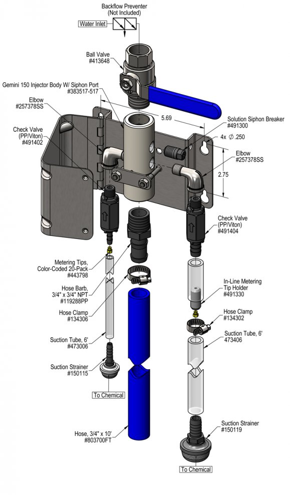
TO SET DILUTION RATIO, thread a color-coded metering tip into each tip holder. See chemical labels for dilution ratio recommendation or consult your chemical supplier.

  • For the strongest dilution ratio do NOT install a colored metering tip.
  • The dilution ratios in the metering tip chart are based on water thin chemicals with a viscosity of 1CPS. Thicker chemicals will require a larger tip than the ratios shown in the chart.
  • Chart shows ratios at 40 PSI water pressure. Actual water pressure is shown on unit gauge during operation. Adjust metering tip selection based on actual water pressure using the online Metering Tip Calculator or the math formula shown in the chart.
  • Select and thread the tip color that is closest to your desired chemical strength into the tip holder.  DO NOT OVER-TIGHTEN
  • Application results will ultimately determine final tip color selection.
  • Push the chemical tubes over the tip holders and place the strainer in the chemical concentrate.
  • If necessary, cut suction tube(s) to length.

If a leaner solution than the maximum shown in the chart is required, it will be necessary to use one proportioner to pre-dilute the concentrate, and a second to dilute the resulting solution to the required final ratio. If this Double Dilution procedure is required, choose two metering tips whose ratios, when multiplied together, result in a ratio that is as close as possible to the required final ratio. Example: For two "Bottle Fill" Mixing Station valves with 40 PSI water pressure, use a White Tip (37:1) and a Corn Yellow Tip (21:1) to achieve a final solution ratio of 777:1.

To Operate

  1. Hold the discharge hose inside the container to be filled, do not release it,  and completely open the appropriate inlet ball valve. 
  2. When container is filled to the desired level, close the ball valve and keep the discharge tube in the container until it completely drains before removing it.
  3. Make final metering tip adjustments based on application results. Try the next larger or smaller sized metering tip until the results are acceptable.

Metering Tip Selection

Metering Tip Color
OZ/MIN
Dilution Ratio
@ 40 PSI
1/2'' Tube1/4'' Tube
Brown
0.561600:11600:1
Clear
0.881018:11018:1
Bright Purple
1.38649:1649:1
White
2.15417:1417:1
Pink
2.93306:1306:1
Corn Yellow
3.84233:1233:1
Dark Green
4.88184:1184:1
Orange
5.77155:1155:1
Gray
6.01149:1149:1
Light Green
7.01128:1128:1
Med. Green
8.06111:1111:1
Clear Pink
9.4395:195:1
Yellow Green
11.5078:178:1
Burgundy
11.9375:175:1
Pale Pink
13.8765:165:1
Light Blue
15.1459:159:1
Dark Purple
17.8850:150:1
Navy Blue
25.3635:135:1
Clear Aqua
28.6031:131:1
Black
50.0018:118:1
No Tip Ratio Up To:6.1:18.5:1
The dilution ratios above are approximate values. Due to chemical viscosity, actual dilution ratios may vary.

Formula

GPM × 128 ÷ Desired Dilution Ratio = oz/min

  • See Unit Flow Rates chart for GPM
  • Use 20 for 20:1 dilution ratio, 30 for 30:1, etc.
  • Match calculated ounces per minute (oz/min) to nearest oz/min in Metering Tip Selection chart.

Unit Flow Rates

PSIGPM
1/2'' Tube1/4'' Tube
356.556.55
407.007.00
507.837.83
608.578.57
709.269.26
809.909.90
9010.5010.50
10011.0711.07
11011.6111.61
12012.1212.12
12512.3712.37
982150.jpg
Troubleshooting Guide
Problem Possible Cause / Solution
StartupMaintenance
A) Unit will not draw chemical.
B) Dilution too weak.
C) Dilution too strong
D) Water backing up into chemical container.
E) Vacuum breaker constantly dripping / leaking.
1, 2, 3
4
5
6, 7, 8, 9, 10, 11
11

8
12, 13
Possible Cause / Solution
StartupMaintenance
  1. Water pressure too low or water temperature too high
    • See requirements.
  2. Ball valve not completely open
    • Completely open the ball valve.
  3. Chemical tube not immersed in chemical or chemical depleted
    • Immerse tube or replenish.
  4. Metering tip too small
    • Install larger metering tip.
  5. No metering tip installed or metering tip too large
    • Install smaller metering tip.
  1. Water inlet strainer screen clogged
    • Disconnect water and clean the screen.
  2. Chemical strainer or metering tip partially blocked
    • Clean or replace chemical strainer and/or metering tip.
  3. Check valve stuck or failed
    • Clean or replace.
  4. Vacuum leak in chemical pick-up connections
    • Tighten the connection.
  5. Chemical tube stretched out where tube slides over metering tip holder or pin hole/cut in chemical tube (sucking air in)
    • Cut off end of tube or replace tube.
  6. Water scale or chemical build-up may have formed in the body causing poor or no chemical pick-up
    • Follow Preventive Maintenance instructions below, using hot water and/or descaling acid. When there is no draw at all, carefully remove fittings and soak entire body in descaling acid.
  7. Vacuum breaker fouled or failed
    • Replace vacuum breaker. 
    • Install filter on water supply line.
  8. Vacuum breaker experiencing backpressure
    • The vacuum breaker(s) will vent water when experiencing backpressure that cannot exist under normal operating conditions.
    • Do not exceed maximum water pressure.  See requirements.
    • Do not modify discharge assembly, attach shutoff valve, or otherwise restrict flow from unit discharge.
    • Descale injector body, if necessary.
PREVENTIVE MAINTENANCE: When the unit will be out of service for extended periods, place chemical tube(s) in water and flush the chemical out of the unit to help prevent chemical from drying out and causing build-up. Periodically check and clean chemical strainer and replace if missing.