Lafferty Equipment Manufacturing, LLC

Installation & Operation Instructions

Model # 977002 · Timed Asphalt Release Sprayer

Requirements

Chemical Concentrate
Water
Temperature up to 160°F
Pressure 35 to 125 PSI
Flow 1.3 GPM @ 40 PSI
Supply Line 1/2"
Hose 1/2" ID x 25'
Nozzle 2540
Electric 120V

Options

Stainless Steel Hose Racks
Small Stainless Steel Hose Rack# 224145
Drum & Tote Stick Lengths & Seal Materials
Drum Stick, 33" (Viton or EPDM)# 491643 / 491643-E
Drum Stick, 48" (Viton or EPDM)# 491648 / 491648-E
Drum Stick, 54" (Viton or EPDM)# 491645 / 491645-E
Tote Stick, 33" (Viton or EPDM)# 491653 / 491653-E
Tote Stick, 48" (Viton or EPDM)# 491654 / 491654-E
Tote Stick, 54" (Viton or EPDM)# 491656 / 491656-E
Alternate Chemical Check Valve - Viton Standard
Check Valve, Chemical, PP(W), 1/4" (EPDM)# 491401
977002
AR_spraywand-OBV.jpg
Warning! Read All Instructions Before Using Equipment!

Overview

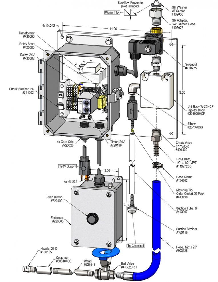
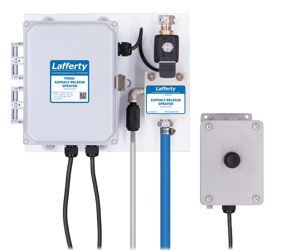
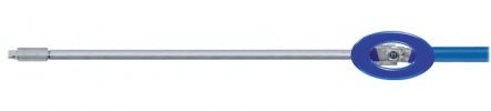
The Timed Asphalt Release Spray-All is a water-driven, time-delayed spray applicator for applying asphalt release chemicals on to truck beds or tools to prevent asphalt from sticking. This venturi injection system uses standard city water pressure (35 - 125 PSI) to draw and blend chemical concentrate into the water stream. Precision metering tips are used to create an accurately diluted solution which is projected through the discharge hose and fan nozzle as a uniform spray. With a flow rate of around 1.3 GPM @ 40 PSI, this unit is great for spraying down any sized vehicle or equipment quickly and efficiently. This unit features an adjustable dual-function timer which controls the length of application and the delay time which keeps the driver from immediately restarting the system, preventing costly over-application.

Safety & Operational Precautions

  • When connecting to a potable water supply follow all local codes for backflow prevention.
  • See Additional Safety Precautions included with the Electrical Control Box Installation Information
  • Always consider electrical shock hazard when working with and handling electrical equipment. If uncertain, consult an Electrician. Electrical wiring should only be done by a qualified Electrician.
  • For proper performance do NOT modify, substitute nozzle, hose diameter or electrical control box.
  • Manufacturer assumes no liability for the use or misuse of this unit.
  • Wear protective clothing, gloves and eye wear when working with chemicals.
  • Always direct the discharge away from people and electrical devices.
  • Follow the chemical manufacturer's safe handling instructions.
  • NEVER mix chemicals without first consulting chemical manufacturer.
  • Disconnect electrical power to the control box prior to opening it.
  • If the control box is connected to compressed air, the compressed air pressure should be kept to a maximum of 90 PSI.

To Install (refer to diagram on next page)

If you are connecting to a potable water supply follow all local codes for backflow prevention.

  1. Do NOT connect to electricity yet.
  2. Mount the unit to a suitable surface above the chemical supply to prevent siphoning.
  3. Connect the discharge hose as shown in the diagram.
  4. Connect water supply. If water piping is older, or has known contaminants, install a filter.
  5. Mount the push button activation control box.

Set the chemical dilution ratio by threading one of the color coded metering tips into each chemical check valve. See chemical labels for dilution ratio recommendation or consult your chemical supplier.

  • For the strongest dilution ratio do NOT install a colored metering tip.
  • The dilution ratios in the metering tip chart are based on water thin chemicals with a viscosity of 1CPS.
  • Thicker chemicals will require a larger tip than the ratios shown in the chart.
  • Application results will ultimately determine final tip color.
  • Select the tip color that is closest to your desired chemical strength and thread it into the tip holder. DO NOT OVER-TIGHTEN.
  • Push the chemical tube over the check valve barb and place the suction tube in the chemical concentrate.
  • If necessary, cut suction tube(s) to length before attaching suction strainer.

SETTING THE TIMER

  1. Make sure the system is not plugged in to a power source. Remove control box cover. The box contains one timer with "Run & Delay" adjustment knobs.
    Run: This mode allows you to set the length of time you want the unit to run each time the operator presses the remote button. Turn the knob to set the run time (0-6 Minutes).
    Delay: This mode allows you to set the length of time you want the unit to to be inactive after each application.  Turn the knob to set the delay time (0-6 Minutes).
  2. Replace the control box cover.
  3. Plug the power cord into a 120 VAC power outlet. GFI recommended.
  4. Turn on your air and/or water supply (if applicable).
  5. Push the remote button to activate the timer and make any last adjustments needed.
  6. The unit is ready for operation. The run mode will activate the unit for the preset run time, turn off, and will not reactivate until the time runs out on the delay mode. Then the unit will reset.

TO OPERATE

  1. With the wand in hand push the remote button.
  2. Open the discharge ball valve and begin application.
  3. The run timer will activate the unit for the preset time and turn the unit off. The delay timer will prevent the unit from activating until the preset delay time runs out, then the button will reset.
  4. Make final metering tip adjustments based on results.

Metering Tip Selection

Metering Tip Color
OZ/MIN
Dilution Ratio
@ 40 PSI
Brown
0.56297:1
Clear
0.88189:1
Bright Purple
1.38121:1
White
2.1577:1
Pink
2.9357:1
Corn Yellow
3.8443:1
Dark Green
4.8834:1
Orange
5.7729:1
Gray
6.0128:1
Light Green
7.0124:1
Med. Green
8.0621:1
Clear Pink
9.4318:1
Yellow Green
11.5014:1
Burgundy
11.9314:1
Pale Pink
13.8712:1
Light Blue
15.1411:1
Dark Purple
17.889:1
Navy Blue
25.367:1
Clear Aqua
28.606:1
Black
50.003:1
No Tip Ratio Up To:3:1
The dilution ratios above are approximate values. Due to chemical viscosity, actual dilution ratios may vary.

Formula

GPM × 128 ÷ Desired Dilution Ratio = oz/min

  • See Unit Flow Rates chart for GPM
  • Use 20 for 20:1 dilution ratio, 30 for 30:1, etc.
  • Match calculated ounces per minute (oz/min) to nearest oz/min in Metering Tip Selection chart.

Unit Flow Rates

PSIGPM
351.22
401.30
501.45
601.59
701.72
801.84
901.95
1002.06
1102.16
1202.25
1252.30
977002.jpg
Troubleshooting Guide
Problem Possible Cause / Solution
StartupMaintenance
A) Unit will not draw chemical
B) Asphalt sticking
C) Dilution too strong
D) Water backing up into chemical container
E) Unit doesn't come on when when button is pushed.
F) Unit comes on but no water through the solenoid
1,4,5,6,7
2,4,
3

9,10
1,5,8
11,12,13,14,15,16
11,12,13,14,15,16

11
9,10
10,17
Possible Cause / Solution
StartupMaintenance
  1. Water ball valve not completely open
    • Completely open water ball valve.
  2. Not enough chemical - metering tip too small
    • Install larger metering tip.
  3. No metering tip installed or metering tip too large
    • Install smaller metering tip.
  4. Chemical tube not immersed in chemical or chemical depleted
    • Immerse tube or replenish.
  5. Discharge hose kinked or discharge ball valve no all the way open
    • Straighten the hose/open ball valve completely
  6.  Wrong Nozzle/Wand
    • See requirements
  7. Water pressure or water volume too low/inlet piping too small causing poor chemical pick up
    • Increase water pressure or water volume
  8. No water to the unit
    • Ensure water supply is not shut off to the unit
  9. Timer failed/Controller not set properly or malfunctioned
    • Replace timer. See Controller manual
  10. May have electrical problems
    • Have a qualified electrician check electrical connections. Ensure circuit breaker (5 Amp) has not been tripped.

  1. Chemical check valve stuck or failed
    • Clean or replace.
  2. Chemical strainer or metering tip partially blocked
    • Clean or replace chemical strainer and/or metering tip.
  3. Chemical tube stretched out or pin hole/cut in chemical tube
    • Cut off end of tube or replace tube.
  4. Vacuum leak in chemical pick-up connections
    • Tighten the connection.
  5. Water strainer clogged or missing/injector inlet orifice clogged
    • Clean or replace strainer; check/clean inlet orifice for obstructions. DO NOT DRILL OUT.
  6. Hard water scale or chemical build-up may have formed in the injector body causing poor or no chemical pick-up
    • Follow Preventive Maintenance instructions below, using hot water and/or de-scaling acid. When there is no draw at all, carefully remove fittings and soak entire injector body in de-scaling acid.
  7. Water solenoid clogged or failed
    • Clean or replace the water solenoid
PREVENTIVE MAINTENANCE: When the unit will be out of service for extended periods, place chemical tube(s) in water and flush the chemical out of the unit to help prevent chemical from drying out and causing build-up. Periodically check and clean chemical strainer and replace if missing.