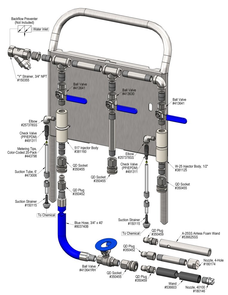
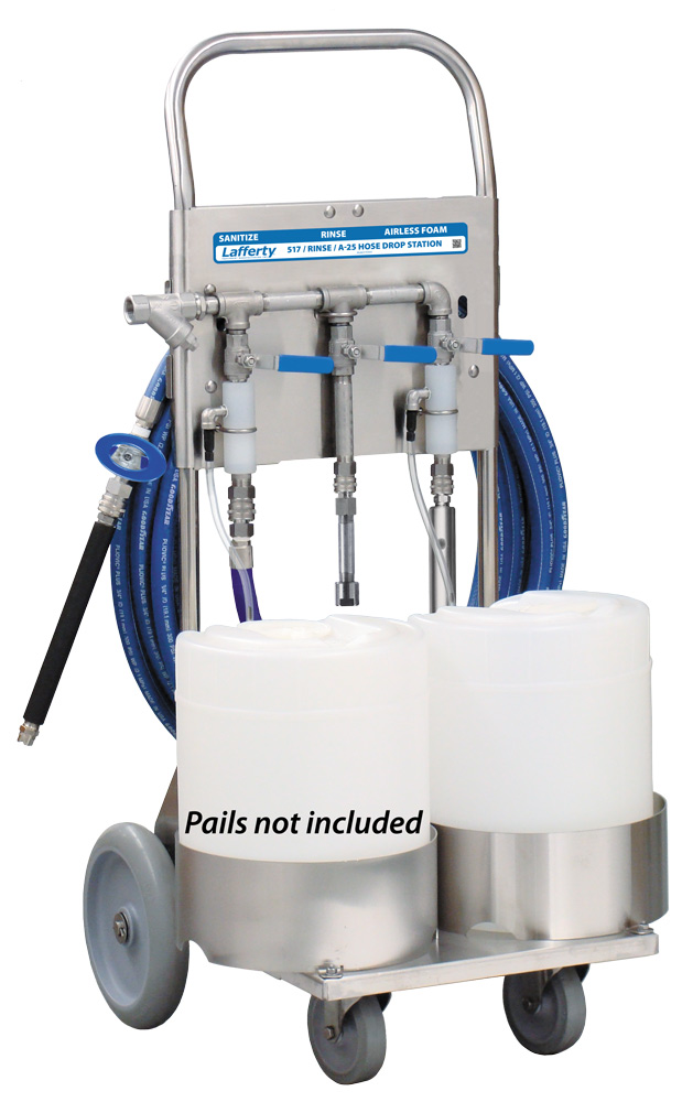
Lafferty Equipment Manufacturing, LLC

Installation & Operation Instructions

Model # 915955 · Portable 517 Sanitize / Rinse / A-25 Airless Foam Hose Drop Station

Requirements

Chemical Concentrate
Water
Temperature up to 160°F
Pressure 35 to 125 PSI
Flow 7.2 GPM @ 40 PSI
Supply Line 3/4"
Hose
Sanitize 3/4" ID x 40'
Rinse 3/4" ID x 40'
Foam 3/4" ID x 40'
Nozzle
Sanitize 40100
Rinse 4 Hole Rinse Nozzle
Foam A-25 Airless Foam Wand

Options

Water Pressure Gauge
Water Pressure Gauge, 3/4" Inlet# 336348
Separate Hose For Incompatible Chemicals
Red Hose Kit, 3/4" x 40'# 807740RQD
Square Jug Rack Conversion
Specify Round or Square Jug Racks at time of order
Alternate Check Valve - EPDM Standard
Check Valve, Chemical, PP/Viton, 1/4"# 491315
915955
Warning! Read All Instructions Before Using Equipment!

Overview

The Portable 517 Sanitize/Rinse/A-25 Airless Foam Hose Drop Station is a combination applicator for applying one chemical as wet airless foam, applying another as a high-volume sanitizing spray, and for rinsing (no compressed air required). Featuring an all stainless steel cart assembly, this venturi injection system uses standard city water pressure (35 - 125 PSI) to draw and blend chemical concentrates into the water streams to create accurately diluted solutions using precision metering tips to control chemical usage. The airless foam wand creates and projects wet, clinging foam at distances up to 6 feet. The sanitizer solution is projected as a "flooding" spray for fast complete coverage. Rinse at full pressure using a unique, powerful 4-hole nozzle.

Safety & Operational Precautions

  • When connecting to a potable water supply follow all local codes for backflow prevention.
  • WARNING: Severe damage to your facility, or contamination of your potable water supply, can occur without proper backflow prevention.
  • For proper performance do NOT modify, substitute nozzle, hose diameter or length.
  • Manufacturer assumes no liability for the use or misuse of this unit.
  • Wear protective clothing, gloves and safety goggles when working with chemicals.
  • Always direct the discharge away from people and electrical devices.
  • For pressures over 100 PSI, remove the discharge valve or lower pressure.
  • Never leave inlet ball valves on when unit is not in use.
  • Follow the chemical manufacturer's safe handling instructions.
  • NEVER mix chemicals without first consulting chemical manufacturer.

To Install (refer to diagram on next page)

  1. Place a container of chemical concentrate in the jug rack(s).
  2. Connect the hose(s) as shown in the diagram.
  3. To prevent blocking the small water jets in the injector flush any new plumbing of debris before connecting water.
  4. Connect water supply. If water piping is older or has known contaminants, install a water filter.

Set the chemical dilution ratio by threading one of the color coded metering tips into each chemical check valve. See chemical labels for dilution ratio recommendation or consult your chemical supplier.

  • For the strongest dilution ratio do NOT install a colored metering tip.
  • The dilution ratios in the metering tip chart are based on water thin chemicals with a viscosity of 1CPS.
  • Thicker chemicals will require a larger tip than the ratios shown in the chart.
  • Application results will ultimately determine final tip color.
  • Select the tip color that is closest to your desired chemical strength and thread it into the tip holder. DO NOT OVER-TIGHTEN.
  • Push the chemical tube over the check valve barb and place the suction tube in the chemical concentrate.
  • If necessary, cut suction tube(s) to length before attaching suction strainer.

To Operate

OPEN ONLY ONE INLET WATER BALL VALVE AT A TIME

TO FOAM

  1. Quick connect airless foam wand to the closed discharge ball valve.
  2. Open the inlet then the discharge ball valves to begin application.
  3. Make final metering tip adjustments based on application results.
  4. When foaming is completed, close the discharge ball valve then close the inlet ball valve.
  5. Briefly re-open the discharge ball valve to relieve pressure in hose. Rinse the work surface before foam dries.

TO RINSE

  1. Relieve pressure in the hose, quick connect the hose to the rinse discharge.
  2. Replace the foam wand with the 4-Hole rinse nozzle. Close the ball valve.
  3. Open the inlet ball valve then the discharge ball valve to begin application.
  4. When rinsing is completed, close the discharge ball valve then close the inlet ball valve.
  5. Briefly re-open the discharge ball valve to relieve pressure in hose.

TO SANITIZE

  1. Make sure to relieve pressure in the hose, securely quick connect it to the sanitizer.
  2. Quick connect the sanitize wand to the ball valve.
  3. Open the inlet and discharge ball valves to begin sanitizing.
  4. Make final metering tip adjustments based on application results.
  5. When sanitizing is completed, close the discharge then inlet ball valves.
  6. Relieve pressure in the hose. Rinse if applicable.

Metering Tip Selection

Metering Tip Color
OZ/MIN
Dilution Ratio
@ 40 PSI
SanitizeRinseFoam
Brown
0.561234:1306:1
Clear
0.88785:1195:1
Bright Purple
1.38501:1124:1
White
2.15321:180:1
Pink
2.93236:159:1
Corn Yellow
3.84180:145:1
Dark Green
4.88142:135:1
Orange
5.77120:130:1
Gray
6.01115:129:1
Light Green
7.0199:124:1
Med. Green
8.0686:121:1
Clear Pink
9.4373:118:1
Yellow Green
11.5060:115:1
Burgundy
11.9358:114:1
Pale Pink
13.8750:112:1
Light Blue
15.1446:111:1
Dark Purple
17.8839:110:1
Navy Blue
25.3627:17:1
Clear Aqua
28.6024:16:1
Black
50.0014:1
No Tip Ratio Up To:11:15:1
The dilution ratios above are approximate values. Due to chemical viscosity, actual dilution ratios may vary.

Formula

GPM × 128 ÷ Desired Dilution Ratio = oz/min

  • See Unit Flow Rates chart for GPM
  • Use 20 for 20:1 dilution ratio, 30 for 30:1, etc.
  • Match calculated ounces per minute (oz/min) to nearest oz/min in Metering Tip Selection chart.

Unit Flow Rates

PSIGPM
SanitizeRinseFoam
355.056.731.25
405.407.201.34
506.048.051.50
606.618.821.64
707.149.521.77
807.6410.181.90
908.1010.802.01
1008.5411.382.12
1108.9511.942.22
1209.3512.472.32
1259.5512.732.37
915955.jpg
Troubleshooting Guide
Problem Possible Cause / Solution
StartupMaintenance
A) Foamer will not draw chemical.
B) Foam does not clean / too wet.
C) Water back flowing into chemical container
D) Solution backing up into water line.

1, 2, 4, 5
1, 2, 6, 7
9
15
9, 10, 11, 12, 13, 14, 16


Problem Possible Cause / Solution
StartupMaintenance
A) Sanitizer will not draw chemical.
B) Using too much chemical.
C) Water back flowing into chemical
D) Solution backing up into water line.
1, 2, 3, 4, 5
8
9
15
9, 10, 12, 13, 14, 16
Possible Cause / Solution
StartupMaintenance
  1. Water pressure too low
    • Increase water pressure. (See Requirements)
  2. Inlet ball valve or discharge ball valve not completely open
    • Completely open the valves.
  3. Nozzle wrong size, too small
    • See requirements.
  4. Discharge too long, wrong size or kinked
    • Straighten hose, see requirements.
  5. Chemical tube not immersed in chemical or chemical depleted
    • Immerse or replenish chemical
  6. Dilution too weak
    • Install larger metering tip.
  7. Improper chemical
    • Ensure product is recommended for foaming and/or the application.
  8. Dilution too strong even with smallest metering tip
    • Some weak dilutions at lower water pressures are impossible to achieve with a single metering tip. Pre-dilute your chemical until desired dilution ratio is achieved. Or order 491307-1/4" Inline Dual Metering Tip Holder.
  1. Chemical check valve stuck or clogged
    • Clean or replace.
  2. Water "Y" strainer screen clogged
    • Clean screen or replace.
  3. Airless Foam Wand screen blocked
    • Dried chemical build-up may be obstructing flow through the screen. Remove fittings and soak the entire wand in de-scaling acid.
  4. Metering tip blocked
    • Clean or replace metering tip.
  5. Chemical tube stretched out where tube slides over check valve or pin hole/cut in chemical tube (sucking air in)
    • Cut off end of tube or replace tube.
  6. Vacuum leak in chemical pick-up connection
    • Tighten the connection.
  7. No backflow preventer installed
    • Install appropriate backflow preventer onto water line.
  8. Chemical build-up or scale may have formed in the body causing poor or no chemical pick-up
    • Remove fittings and soak entire body in de-scaling acid. Replace fittings being careful not to cross thread or over tighten.
PREVENTIVE MAINTENANCE: When the unit will be out of service for extended periods, place chemical tube(s) in water and flush the chemical out of the unit to help prevent chemical from drying out and causing build-up. Periodically check and clean chemical strainer and replace if missing.