Lafferty Equipment Manufacturing, LLC

Installation & Operation Instructions

Model # 941611 · 1-Way FPS MM Transfer System

Requirements

Chemical Concentrate
Static Tank of Water
Compressed Air up to 4 CFM
Hose 1/2" ID x 15'
Nozzle Trigger Gun

Options

Stainless Steel Hose Racks
Small Stainless Steel Hose Rack# 224145
Drum & Tote Sticks Available
Alternate Seal Materials (Santoprene/EPDM Standard)
UPGRADE: Viton Pump & Viton Trigger Gun# 941600-VT
UPGRADE: Kalrez Pump & Viton Trigger Gun# 941600-KT
UPGRADE: Kalrez, ATEX Pump & EPDM Hoses# 941600-ATEX
Alternate Discharge (Trigger Gun Standard)
UPGRADE: Stainless Steel Ball Valve & Wand# 941600-X
941611
Transfer_System_Gun_Assembly.jpg
Warning! Read All Instructions Before Using Equipment!

Overview

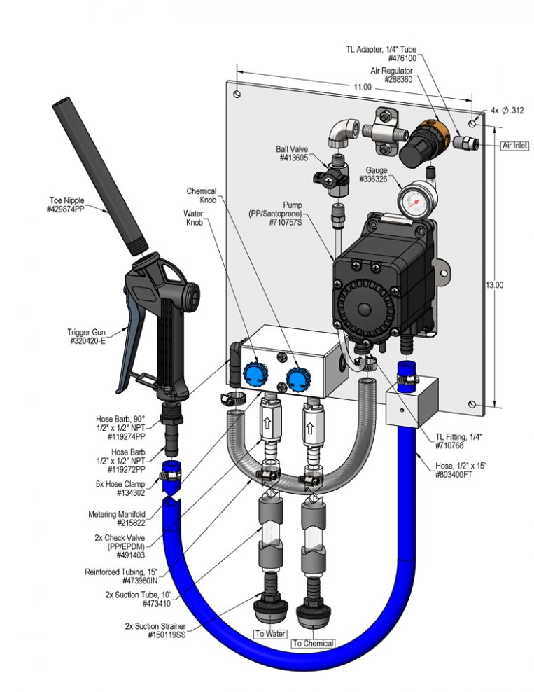
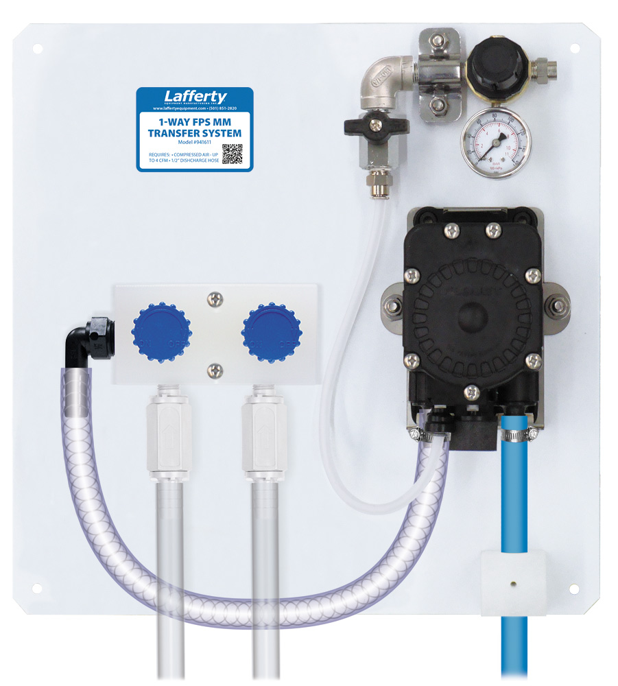
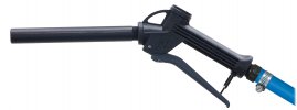
The 1-Way FPS MM Transfer System is a air pump driven chemical transfer system designed to blend 2 compatible chemical concentrates, or 1 chemical concentrate with water, and dispense the solution into any sized container. This unit uses a FloJet air pump to draw the 2 liquids through a unique metering manifold to create virtually any ratio. The solution is then dispensed into any container through a 15 foot discharge hose and trigger gun.

Safety & Operational Precautions

  • For proper performance do NOT modify or substitute hose diameter.
  • Manufacturer assumes no liability for the use or misuse of this unit.
  • Wear protective clothing, gloves and eye-wear when working with chemicals.
  • Always direct the discharge away from people and electrical devices.
  • Follow the chemical manufacturer’s safe handling instructions.
  • DO NOT use d-Limonene or other chemicals that are not compatible with the Santoprene diaphragms.
  • Viton or Kalrez upgrades are available.

To Install (refer to diagram on next page)

  1. Mount the unit above chemical and / or water containers.
  2. Securely attach the suction tubes to the check valves as shown in the drawing.
  3. Place one tube/strainer in the chemical concentrate(s) and the other in a static container of water. (DO NOT use pressurized water!)
  4. Attach a compressed airline to the inlet ball valve. DO NOT TURN ON
How to Set Your Dilution Ratio:
  • The adjustment knobs allow you to achieve wide range of dilution ratios.
  • Turn adjustment knobs counterclockwise to increase flow or clockwise to decrease flow.
  • For a starting place turn the water knob completely clockwise (closed) then turn 2 turns counterclockwise (open).
  • Then turn the chemical knob completely clockwise (closed) then counterclockwise (open) in 1/4 to 1/2 turn increments till required dilution ratios are achieved.
  • If ratios can't be achieved with the chemical knob all the way counterclockwise start turning water knob clockwise to shift more draw to the chemical side.
  • For weaker solutions than the knobs can achieve use a metering tip to further reduce the chemical flow (some units do not include metering tips standard).

To Operate

  1. Final chemical dilution adjustments will now have to be made. Make adjustments to the knobs based on results.
  2. Hold the trigger gun, open the inlet ball valve, place the nozzle in the container to be filled. Pull the trigger and begin.
  3. When container is filled to the desired level, release the trigger. Close the inlet ball valve and pull the trigger to relieve pressure in the hose.
941611.jpg
Troubleshooting Guide
Problem Possible Cause / Solution
StartupMaintenance
A) Air pump will not run or pump chemical solution.
B) Will not draw chemical.
C) Pump runs too fast with no output.


1,3,4
1,2,3
2

5,6,9,10
6,7,8
6,7,8,9

Possible Cause / Solution
StartupMaintenance
  1.  Inlet ball valve partially closed or air pressure too low.
    • Completely open air inlet ball valve.
  2. Chemical tube not immersed in container or container empty
    • Immerse tube or replenish.
  3. Hose kinked
    • Straighten the hose.
  4. Ice particles from condensation in air line — Air pump can periodically "freeze up” (stall) due to ice particles in the pump's exhaust (depending on air humidity & other factors)
    • WAIT several seconds to allow the ice particles to melt and blow out, at which time the pump will automatically resume pumping.
  1. Air regulator clogged or failed
    • Clean or replace.
  2. Chemical strainer clogged up
    • Clean or replace.
  3. Vacuum leak in suction line.
    • Tighten the connection(s).
  4. Chemical tube stretched out where tube attaches or pin hole/cut in tube sucking air.
    • Cut off end of tube or replace tube.
  5. Problem with air pump
  6. Use of an oiler in the airline will cause pump to stall
    • Use only clean, dry air.
PREVENTIVE MAINTENANCE: When the unit will be out of service for extended periods, place chemical tube(s) in water and flush the chemical out of the unit to help prevent chemical from drying out and causing build-up. Periodically check and clean chemical strainer and replace if missing.