| Ready-to-Use Chemical Solution | |
| Temperature | up to 160°F |
| Pressure | 35 to 100 PSI |
| Flow | 4 GPM @ 40 PSI |
| Supply Line | 1/2" Min |
| Compressed Air | up to 6 CFM |
| Hose/Pipe | 1" & 3/4" ID |
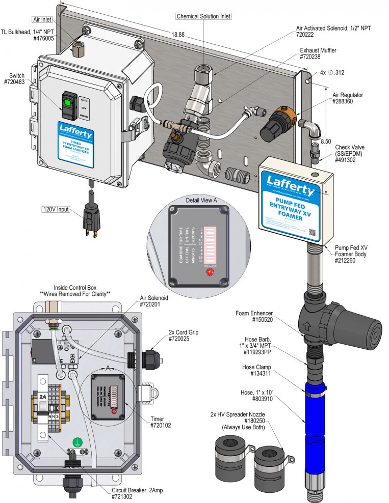
| Nozzle | HV Entryway Spreader (2 - use both) |
| Electric | 120V |
Requirements
| Ready-to-Use Chemical Solution | |
| Temperature | up to 160°F |
| Pressure | 35 to 100 PSI |
| Flow | 4 GPM @ 40 PSI |
| Supply Line | 1/2" Min |
| Compressed Air | up to 6 CFM |
| Hose/Pipe | 1" & 3/4" ID |
| Nozzle | HV Entryway Spreader (2 - use both) |
| Electric | 120V |
Overview
Safety & Operational Precautions
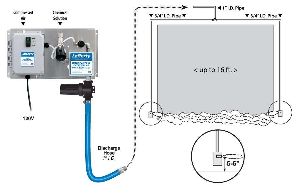
To Install (refer to diagram on next page)
Illustration on Page 1 shows overall system setup. Refer to companion instructions for control box upgrades.
To Operate
TO TEST
TIMER ADJUSTMENT
Unit Flow Rates | |
|---|---|
| PSI | GPM |
| 35 | 3.74 |
| 40 | 4.00 |
| 50 | 4.47 |
| 60 | 4.90 |
| 70 | 5.29 |
| 80 | 5.66 |
| 90 | 6.00 |
| 100 | 6.32 |
Troubleshooting Guide |
|---|
| Problem | Possible Cause / Solution | |
|---|---|---|
| Startup | Maintenance | |
| A) Foam surges. B) Foam output too wet. C) Foam output too dry. D) Unit doesn't come on when switch is turned on. E) Unit comes on and runs continuously. F) Unit comes on but no solution through solenoid. | 1, 2, 3, 4, 6, 7, 8, 9, 10, 11 2, 3, 4, 6, 7, 8, 9, 10, 11 1, 5 11, 12 11 12 |
13, 15, 16 13, 14, 15, 16 13, 14 15 |
| Possible Cause / Solution | |
|---|---|
| Startup | Maintenance |
|
|
PREVENTIVE MAINTENANCE: When the unit will be out of service for extended periods, run water through the system to flush the chemical and help prevent chemical build-up. |