Lafferty Equipment Manufacturing, LLC

Installation & Operation Instructions

Model # 918095 · Shackle Brush Foamer

Requirements

Chemical Concentrate
Water
Temperature up to 180°F
Pressure 400 to 1000 PSI
Flow 0.9 GPM @ 700 PSI
Supply Line 1/2"
Compressed Air up to 3 CFM
Hose 3/8" ID x 50'
Nozzle Spreader Nozzle (#180357) or 40100

Options

Stainless Steel Hose Racks
Large Stainless Steel Hose Rack# 224150
Drum & Tote Stick Lengths & Seal Materials
Drum Stick, 33" (Viton or EPDM)# 491643 / 491643-E
Drum Stick, 48" (Viton or EPDM)# 491648 / 491648-E
Drum Stick, 54" (Viton or EPDM)# 491645 / 491645-E
Tote Stick, 33" (Viton or EPDM)# 491653 / 491653-E
Tote Stick, 48" (Viton or EPDM)# 491654 / 491654-E
Tote Stick, 54" (Viton or EPDM)# 491656 / 491656-E
Alternate Check Valves - EPDM Standard
Check Valve, Chemical, SS, Viton, 1/4"# 491324-V
Check Valve, Air, SS, 1/4" MM (Viton / Hast)# 491306
918095
Warning! Read All Instructions Before Using Equipment!

Overview

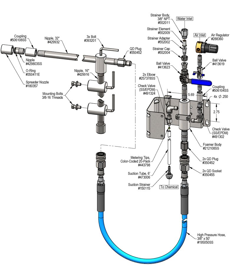
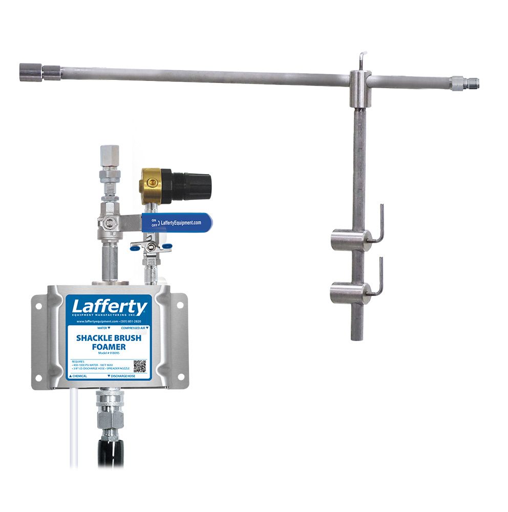
The Shackle Brush Foamer is a low volume foam applicator for projecting foaming chemicals down into shackle brush cabinets. This stainless steel venturi injection system uses high water pressure (400 - 1000 PSI) to draw and blend chemical concentrate into the water stream to create an accurately diluted solution. Rich, clinging foam is created by injecting compressed air into the solution to greatly increase volume and coverage ability. Foam then flows through the discharge hose, adjustable arm and Spreader Nozzle™ – and is projected into the brushes.

Safety & Operational Precautions

  • For proper performance do NOT modify, substitute nozzle, hose diameter or length.
  • Manufacturer assumes no liability for the use or misuse of this unit.
  • Wear protective clothing, gloves and eye wear when working with chemicals.
  • Always direct the discharge away from people and electrical devices.
  • Follow the chemical manufacturer's safe handling instructions.

To Install (refer to diagram on next page)

  1. Mount the unit to a suitable surface above the chemical supply to prevent siphoning.
  2. Connect the discharge hose.
  3. When connecting to a potable water supply follow all local codes for backflow prevention.
  4. Connect water supply. To prevent blocking the small water jets in the foamer body, flush any new plumbing of debris before connecting. If water piping is older and has known contaminants, install a filter.
  5. Connect air supply. If air line is older and has known contaminants install a filter.

ADJUSTABLE ARM WITH SPREADER NOZZLE

  1. Mount slide brackets to suitable nearby surface.  Slide brackets include 3/8-16 threads to accommodate mounting bolts.
  2. Slide the arm through mounted slide bolts and affix end cap.
  3. Position the arm.  Loosen L-bolts on arm(s) and lock at the desired horizontal and vertical positions for testing.  Only adjust one position at a time.
  4. Connect discharge hose from unit as shown in the diagram.

Set the chemical dilution ratio by threading one of the color coded metering tips into each chemical check valve. See chemical labels for dilution ratio recommendation or consult your chemical supplier.

  • For the strongest dilution ratio do NOT install a colored metering tip.
  • The dilution ratios in the metering tip chart are based on water thin chemicals with a viscosity of 1CPS.
  • Thicker chemicals will require a larger tip than the ratios shown in the chart.
  • Application results will ultimately determine final tip color.
  • Select the tip color that is closest to your desired chemical strength and thread it into the tip holder. DO NOT OVER-TIGHTEN.
  • Push the chemical tube over the check valve barb and place the suction tube in the chemical concentrate.
  • If necessary, cut suction tube(s) to length before attaching suction strainer.

To Operate

Always make sure the nozzle is secured and pointed in a safe direction before turning water and air on. DO NOT kink the hose to stop foam flow, return to the unit and close the water and air ball valves

  1. Completely open water and air ball valves.
  2. Wait a few seconds for output to stabilize and observe foam consistency.
  3. To adjust foam consistency, pull out on the air regulator knob. Turn slightly clockwise for dryer foam and counterclockwise for wetter foam. Wait a few seconds to see the result of each adjustment.
    • Use the least amount of air needed to achieve good foam quality to prevent water pressure fluctuations from affecting performance.
    • Medium wet foam will give the best cleaning results. Dry foam will NOT clean as well!
    • You may also have to try different sized metering tips and air settings until foam consistency and cleaning results are acceptable. Once this is set and desired foam consistency is achieved, push lock the knob on the air regulator. You are ready to start application.
  4.  Adjust position and orientation of foam arm and nozzle to achieve desired coverage.
    • Coverage width increases with distance from object being foamed.
    • TIP: If unable to achieve the desired distance from belt due to space constraints, angle the arm so the nozzle projects foam outward instead of straight down.  Spreader Nozzles can be rotated to project into inaccessible spaces.
  5. When foaming is complete:
    • Close water ball valve.
    • Allow hose to empty.
    • Close air ball valve.
    • Disconnect hose from foam arm.
    • Collapse foam arm (if desired).

Metering Tip Selection

Metering Tip Color
OZ/MIN
Dilution Ratio
@ 700 PSI
Brown
0.56203:1
Clear
0.88129:1
Bright Purple
1.3882:1
White
2.1553:1
Pink
2.9339:1
Corn Yellow
3.8430:1
Dark Green
4.8823:1
Orange
5.7720:1
Gray
6.0119:1
Light Green
7.0116:1
Med. Green
8.0614:1
Clear Pink
9.4312:1
Yellow Green
11.5010:1
Burgundy
11.9310:1
Pale Pink
13.878:1
Light Blue
15.147:1
Dark Purple
17.886:1
Navy Blue
25.364:1
Clear Aqua
28.604:1
Black
50.00
No Tip Ratio Up To:3.7:1
The dilution ratios above are approximate values. Due to chemical viscosity, actual dilution ratios may vary.

Formula

GPM × 128 ÷ Desired Dilution Ratio = oz/min

  • See Unit Flow Rates chart for GPM
  • Use 20 for 20:1 dilution ratio, 30 for 30:1, etc.
  • Match calculated ounces per minute (oz/min) to nearest oz/min in Metering Tip Selection chart.

Unit Flow Rates

PSIGPM
4000.67
5000.75
6000.82
7000.89
8000.95
9001.01
10001.06
918095.jpg
Troubleshooting Guide
Problem Possible Cause / Solution
StartupMaintenance
A) Foam surges and/or hose "bucks".
B) Foamer will not draw chemical.
C) Foam too wet.
D) Foam does not clean properly (too dry).
E) Using too much chemical.
F) Water/chemical backing up into air line.
G) Water backing up into chemical container.
H) Air/chemical solution backing up into water line.
1, 2, 3, 4, 6, 7, 8, 9, 10
1, 3, 4, 7, 8, 9, 10
2, 3, 4, 6, 7, 8, 9, 10
1, 4, 6, 11
5
12, 13, 14, 15, 16, 18, 19
12, 13, 14, 15, 16, 18, 19
13, 14, 15, 16, 18, 19


17
18
20
Possible Cause / Solution
StartupMaintenance
  1. Air pressure too high
    • Adjust the air regulator slowly counterclockwise until output stabilizes.
  2. Water pressure or water volume too low/inlet piping too small causing poor chemical pick up
    • Increase water pressure or water volume (SEE REQUIREMENTS).
  3. Inlet or chemical (2 & 3-Way) ball valve not completely open,
    • Completely open the inlet, discharge, and chemical valves.
  4. Not enough chemical - metering tip too small
    • Install larger metering tip.
  5. No metering tip installed or metering tip too large
    • Install smaller metering tip.
  6. Improper chemical
    • Ensure product is recommended for foaming and the application.
  7. Chemical tube not immersed in chemical or depleted
    • Immerse tube or replenish.
  8. Discharge hose too long or wrong size or kinked
    • Straighten the hose or replace hose with correct size and length.
  9. Nozzle size too small
    • Replace nozzle with correct size.
  10. Use of an oiler in the airline will cause poor foam quality
    • Use only clean, dry air.
  11. Soil has hardened on surface, rinse foam before it dries
    • Reapplication may be necessary.
  1. Foamer inlet orifice clogged
    • Check/clean inlet orifice for obstructions. DO NOT DRILL OUT. Install a water filter.
  2. Chemical strainer or metering tip partially blocked
    • Clean or replace chemical strainer and/or metering tip.
  3. Chemical tube stretched out or pin hole/cut in chemical tube sucking air.
    • Cut off end of tube or replace tube.
  4. Vacuum leak in chemical pick-up connections
    • Tighten the connection.
  5. Air regulator failed allowing too much air or not enough air
    • Clean or replace.
  6. Air check valve failed
    • Clean or replace.
  7. Chemical check valve stuck or failed
    • Clean or replace.
  8. Hard water scale or chemical build-up may have formed in the foamer body causing poor or no chemical pick-up
    • Follow Preventive Maintenance instructions below, using hot water or descaling acid. When there is no draw at all, carefully remove fittings and soak entire body in descaling acid.
  9. No backflow preventer installed and/or inlet ball valve left on when not in use
    • Install appropriate backflow preventer into water line.
PREVENTIVE MAINTENANCE: When the unit will be out of service for extended periods, place chemical tube(s) in water and flush the chemical out of the unit to help prevent chemical from drying out and causing build-up. Periodically check and clean chemical strainer and replace if missing.