Lafferty Equipment Manufacturing, LLC

Installation & Operation Instructions

Model # 975910 · Conveyor-Mate™ 315 Sanitizer System

Requirements

Chemical Concentrate
Water
Temperature up to 160°F
Pressure 35 to 125 PSI
Flow 4 GPM @ 40 PSI
Supply Line 1/2"
Hose 1/2" ID x 50'
Nozzle 40100 or 100 Spreader

Options

Stainless Steel Hose Racks
Large Stainless Steel Hose Rack# 224150
Stainless Steel Jug Racks
1 Gallon Round/Square# 224200
1 Gallon Round/Square Locking# 224200-L
2 ½ Gallon (8 ½" x 10 ½")# 224210
5 Gallon Round/Square Locking (12" x 12")# 224214
5 Gallon Round/Square (12" x 12")# 224215
Alternate Sanitizer Check Valve - Viton Standard
Check Valve, Chemical, PP/EPDM, 1/4"# 491311
Stainless Steel Wand (Upgrade)
Convert PP Wand to SS (New Units)# 536603-X
975910
Warning! Read All Instructions Before Using Equipment!

Overview

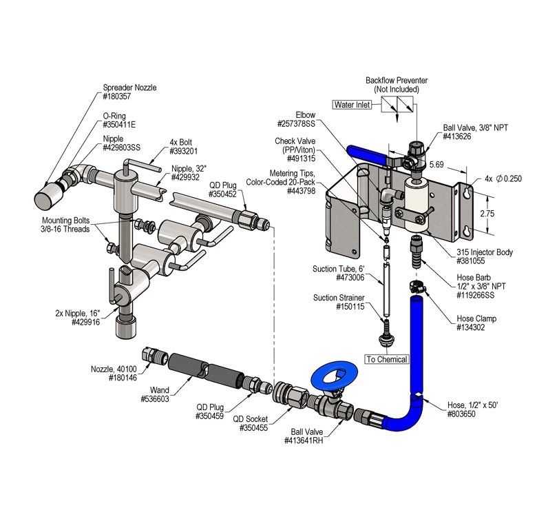
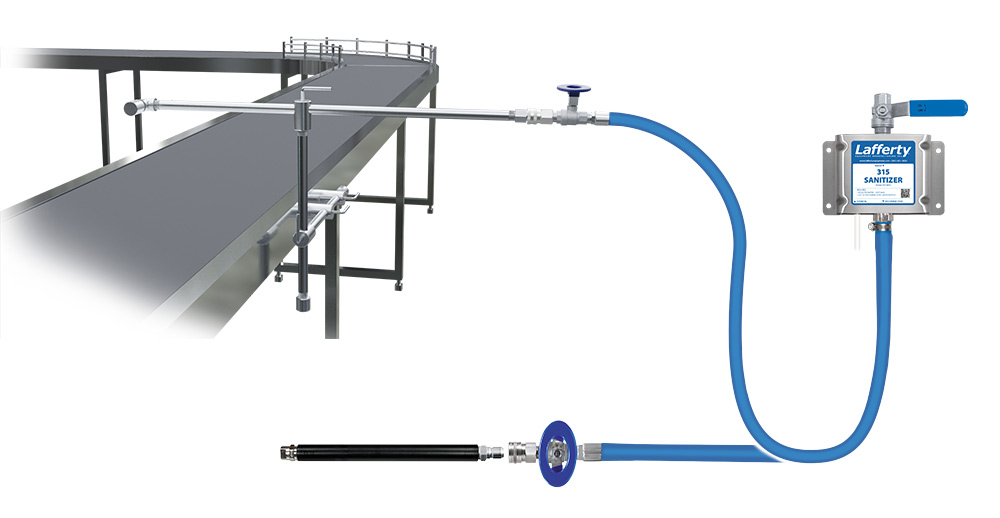
The Conveyor-Mate™ 315 Sanitizer System is specialized for Clean-In-Place spray sanitizing of conveyor belts and also can be used as a manual sanitizer. The stainless steel spray arm and nozzle assembly can be permanently or temporarily mounted to the conveyor belt housing or nearby surface. The fully adjustable spray arm extends vertically and horizontally to virtually any position. The unique stainless steel Spreader Nozzle™ creates a wide spray pattern that can be adjusted and rotated to ensure optimal coverage at any angle. The included 315 Sanitizer is a venturi dilution system that uses city water pressure (35 - 125 PSI) to accurately draw and blend chemical concentrate into the water stream. The solution is then projected through the discharge hose to the spray arm. Quick disconnect the spray arm and attach a wand for manual sanitizing.

Safety & Operational Precautions

  • When connecting to a potable water supply follow all local codes for backflow prevention.
  • WARNING: Severe damage to your facility, or contamination of your potable water supply, can occur without proper backflow prevention.
  • For proper performance do NOT modify, substitute nozzle, hose diameter or length.
  • Manufacturer assumes no liability for the use or misuse of this unit.
  • Wear protective clothing, gloves and safety goggles when working with chemicals.
  • Always direct the discharge away from people and electrical devices.
  • For pressures over 100 PSI, remove the discharge valve or lower pressure.
  • Never leave inlet ball valves on when unit is not in use.
  • Follow the chemical manufacturer's safe handling instructions.
  • NEVER mix chemicals without first consulting chemical manufacturer.

To Install (refer to diagram on next page)

If you are connecting to a potable water supply follow all local codes for backflow prevention.

  1. Mount the unit to a suitable surface above the chemical supply to prevent siphoning.
  2. Connect hose(s) as shown in the diagram.
  3. Flush any new plumbing of debris before connecting water.
  4. Connect water supply. Install a water filter if water piping is older or has known contaminants.

ADJUSTABLE ARM WITH SPREADER NOZZLE

  1. Mount slide brackets to suitable nearby surface.  Slide brackets include 3/8-16 threads to accommodate mounting bolts.
  2. Slide the arm through mounted slide bolts and affix end cap.
  3. Position the arm.  Loosen L-bolts on arm(s) and lock at the desired horizontal and vertical positions for testing.  Only adjust one position at a time.
  4. Connect discharge hose from unit as shown in the diagram.

Set the chemical dilution ratio by threading one of the color coded metering tips into each chemical check valve. See chemical labels for dilution ratio recommendation or consult your chemical supplier.

  • For the strongest dilution ratio do NOT install a colored metering tip.
  • The dilution ratios in the metering tip chart are based on water thin chemicals with a viscosity of 1CPS.
  • Thicker chemicals will require a larger tip than the ratios shown in the chart.
  • Application results will ultimately determine final tip color.
  • Select the tip color that is closest to your desired chemical strength and thread it into the tip holder. DO NOT OVER-TIGHTEN.
  • Push the chemical tube over the check valve barb and place the suction tube in the chemical concentrate.
  • If necessary, cut suction tube(s) to length before attaching suction strainer.

To Operate

Always make sure the discharge ball valve is closed or pointed in a safe direction before turning water on. Ball valve can be shut off at any time during operation but should not be left unattended for long periods of time.

  1. Open the inlet ball valve then open the discharge ball valve to begin application.
  2. Make final metering tip adjustments based on application results.
  3. When application is completed, close the discharge ball valve, return to the unit and close the inlet ball valve. Re-open the discharge ball valve to relieve pressure in hose then close the discharge ball valve. If applicable rinse the work surface before solution dries.

CONVEYOR-MATE ARM WITH SPREADER NOZZLE

  1. Close discharge ball valve and use quick disconnects to switch between hand-held wand and Conveyor-Mate arm. 
  2. Adjust position and orientation of arm and nozzle to achieve desired coverage.
    • NOTE: Coverage width increases with distance from object.
      • 28" distance = 48" coverage
    • TIP:  If unable to achieve the desired distance from belt due to space constraints, angle the arm so the nozzle projects outward instead of straight down.  Nozzles can be rotated if they cannot be positioned over belt center.

Metering Tip Selection

Metering Tip Color
OZ/MIN
Dilution Ratio
@ 40 PSI
Brown
0.56914:1
Clear
0.88582:1
Bright Purple
1.38371:1
White
2.15238:1
Pink
2.93175:1
Corn Yellow
3.84133:1
Dark Green
4.88105:1
Orange
5.7789:1
Gray
6.0185:1
Light Green
7.0173:1
Med. Green
8.0664:1
Clear Pink
9.4354:1
Yellow Green
11.5045:1
Burgundy
11.9343:1
Pale Pink
13.8737:1
Light Blue
15.1434:1
Dark Purple
17.8829:1
Navy Blue
25.3620:1
Clear Aqua
28.6018:1
Black
50.0010:1
No Tip Ratio Up To:9:1
The dilution ratios above are approximate values. Due to chemical viscosity, actual dilution ratios may vary.

Formula

GPM × 128 ÷ Desired Dilution Ratio = oz/min

  • See Unit Flow Rates chart for GPM
  • Use 20 for 20:1 dilution ratio, 30 for 30:1, etc.
  • Match calculated ounces per minute (oz/min) to nearest oz/min in Metering Tip Selection chart.

Unit Flow Rates

PSIGPM
353.74
404.00
504.47
604.90
705.29
805.66
906.00
1006.32
1106.63
1206.93
1257.07
975910.jpg
Troubleshooting Guide
Problem Possible Cause / Solution
StartupMaintenance
A) Unit will not draw chemical
B) Dilution too weak
C) Dilution too strong
D) Water backing up into chemical container
1, 4, 5, 6, 7
2, 4, 5
3
8, 9, 10, 11, 12, 13, 14
8, 9, 10, 11, 12, 13, 14
14
8
Possible Cause / Solution
StartupMaintenance
  1. Inlet or discharge ball valves not completely open
    • Completely open both ball valves.
  2. Not enough chemical - metering tip too small
    • Install larger metering tip.
  3. No metering tip installed or metering tip too large
    • Install smaller metering tip.
  4. Chemical tube not immersed in chemical or chemical depleted
    • Immerse tube or replenish.
  5. Discharge hose too long for available water pressure, kinked or wrong size
    • Straighten the hose or replace hose.
  6. Nozzle size too small (SEE REQUIREMENTS)
  7. Water pressure or water volume too low/inlet piping too small causing poor chemical pick up
    • Increase water pressure or water volume
  1. Chemical check valve stuck or failed
    • Clean or replace.
  2. Chemical strainer or metering tip partially blocked
    • Clean or replace chemical strainer and/or metering tip.
  3. Chemical tube stretched out or pin hole/cut in chemical tube
    • Cut off end of tube or replace tube.
  4. Vacuum leak in chemical pick-up connections
    • Tighten the connection.
  5. Water strainer clogged or missing/injector inlet orifice clogged
    • Clean or replace strainer; check/clean inlet orifice for obstructions. DO NOT DRILL OUT.
  6. Hard water scale or chemical build-up may have formed in the injector body causing poor or no chemical pick-up
    • Follow Preventive Maintenance instructions below, using hot water and/or de-scaling acid. When there is no draw at all, carefully remove fittings and soak entire injector body in de-scaling acid.
  7. More than one chemical ball valve is open
    • 2-Way and 3-Way models only
PREVENTIVE MAINTENANCE: When the unit will be out of service for extended periods, place chemical tube(s) in water and flush the chemical out of the unit to help prevent chemical from drying out and causing build-up. Periodically check and clean chemical strainer and replace if missing.