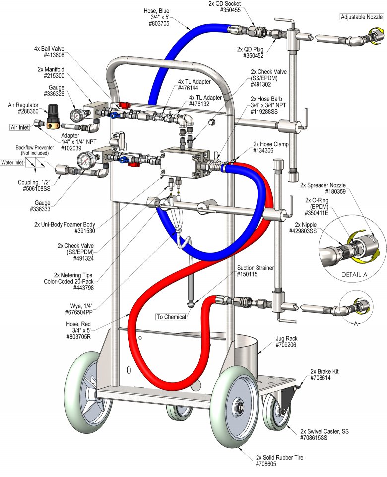
| Hose | 3/4" ID x 5' |
Lafferty Equipment Manufacturing, LLC
Installation & Operation Instructions
Model # 975932 · Portable 5 Gallon Conveyor-Mate™ LC / LC Foam System
Requirements
| Chemical Concentrate |
|---|
| Water | |
|---|---|
| Temperature | up to 160°F |
| Pressure | 35 to 125 PSI |
| Flow | 1.34 GPM @ 40 PSI |
| Supply Line | 1/2" |
| Compressed Air | up to 3 CFM |
| Nozzle | 200 Spreader |
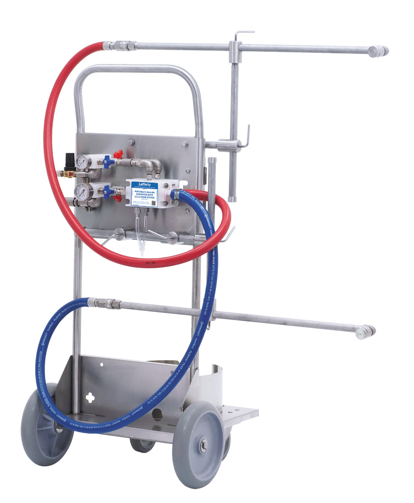
Overview
The LC/LC Conveyor-Mate™ is a portable foaming system designed specifically for Clean-In-Place foaming on to conveyor belts up to 48" wide. This venturi dilution system uses city water pressure (35 - 125 PSI) to accurately draw and blend chemical concentrate into the water stream. Compressed air is added to create rich clinging foam. Dual foamer bodies operate independently for one side only or simultaneously for the top and underside. Fully adjustable foam arms extend vertically and horizontally to virtually any position. The unique stainless steel Spreader Nozzles™ create a wide foam pattern that can be adjusted and rotated to ensure optimal coverage at any angle.