Lafferty Equipment Manufacturing, LLC

Installation & Operation Instructions

Model # 943315 · Freedom 315 Sanitize / LC Foam Hose Drop Station

Requirements

Chemical Concentrate
Water
Temperature up to 160°F
Pressure 20 - 60 PSI / or Static*
Flow w/Pump Air @ 60 PSI
  Sanitize 4.47 GPM
  Foam 1.50 GPM
Supply Line 3/4"

*To use with static water supply, attach the included 3/4" x 5' water suction hose without water regulator.

Compressed Air up to 9 CFM
Hoses
Sanitize 1/2" x 50'
Foam 3/4" x 50'
Nozzle
Sanitize 40100
Foam 50250

Options

Stainless Steel Hose Racks
Large Stainless Steel Hose Rack# 224150
Stainless Steel Jug Racks
2 ½ Gallon (8 ½" x 10 ½")# 224210
5 Gallon Round/Square Locking (12" x 12")# 224214
5 Gallon Round/Square (12" x 12")# 224215
Drum & Tote Sticks Available
Alternate Chemical Check Valve - EPDM Standard
Check Valve, Chemical, PP, 1/4" (Viton)# 491402
Alternate Air Check Valve - EPDM Standard
Check Valve, Air, SS, 1/4" MM (Viton / Hast)# 491306
943315
Warning! Read All Instructions Before Using Equipment!

Overview

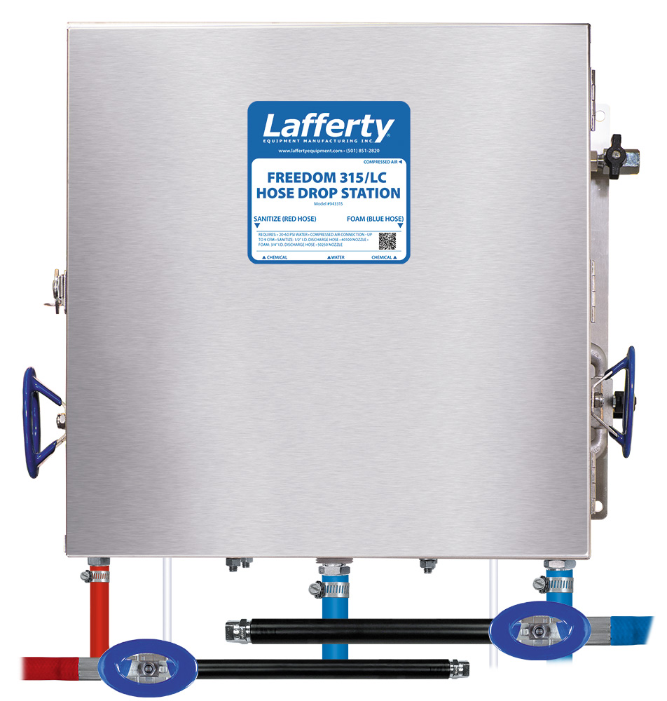
The Freedom 315 Sanitize / LC Foam Hose Drop Station is designed to overcome low or fluctuating water pressure issues, and is a medium volume venturi applicator for applying one chemical as foam and another as a sanitizing spray. It accepts incoming water pressure from 20 to 60 PSI then regulates and maintains the pressure for consistent output. Also, it is adaptable to draw static water from a supply tank. 

A lockable, stainless steel cabinet protects components, including the polypropylene foamer and sanitizer bodies, which draw and blend chemical concentrates into the water stream to create accurately diluted solutions. Compressed air is injected into the foaming solution to greatly increase its volume and coverage ability as rich, clinging foam that is projected through the hose, wand and nozzle up to 10 feet. The sanitizer solution is projected as a "flooding" spray for fast, complete coverage.

Safety & Operational Precautions

  • For proper performance do NOT modify, substitute nozzle, hose diameter or length.
  • Manufacturer assumes no liability for the use or misuse of this unit.
  • Wear protective clothing, gloves and eye-wear when working with chemicals.
  • Always direct the discharge away from people and electrical devices.
  • Follow the chemical manufacturer’s safe handling instructions.
  • Do NOT use chemicals that are incompatible with the pump diaphragms
  • Must use clean dry air!

To Install (refer to diagram on next page)

  1. Mount the unit to a suitable surface above the chemical supply to prevent siphoning.
  2. Connect the discharge hoses as shown in the diagram and close the inlet ball valves.
  3. Flush any new plumbing of debris.
  4. Attach 3/4" x 6" hose to unit and attach water regulator to hose. Connect water supply to regulator.
    • To use static water supply instead, connect 3/4" x 5' hose to unit (without water regulator) and place other end of hose into water tank.
  5. Connect compressed air supply. If piping is older and has known contaminants, install a filter.

Set the chemical dilution ratio by threading one of the color coded metering tips into each chemical check valve. See chemical labels for dilution ratio recommendation or consult your chemical supplier.

  • For the strongest dilution ratio do NOT install a colored metering tip.
  • The dilution ratios in the metering tip chart are based on water thin chemicals with a viscosity of 1CPS.
  • Thicker chemicals will require a larger tip than the ratios shown in the chart.
  • Application results will ultimately determine final tip color.
  • Select the tip color that is closest to your desired chemical strength and thread it into the tip holder. DO NOT OVER-TIGHTEN.
  • Push the chemical tube over the check valve barb and place the suction tube in the chemical concentrate.
  • If necessary, cut suction tube(s) to length before attaching suction strainer.

TO FOAM

  • Always make sure the discharge ball valve is closed or pointed in a safe direction before turning the air on. Ball valve can be shut off at any time during operation but should not be left unattended for long periods of time. Expect a strong blast when re-opening ball valve.
  • The unit has been tested and is ready to operate. The pump air pressure regulator is preset and locked at 60 PSI. This is the optimum pump pressure for this unit. (Do not change the air pressure setting.)
  • Test foam output "as is" before making any foam consistency adjustments.
  1. Final dilution ratios and air adjustments will now have to be made.
  2. The foam consistency knob is pre-set. IF adjustments are needed turn the foam consistency needle valve counterclockwise  for drier foam and clockwise  for wetter foam. Make only small turns and wait several seconds after each adjustment to see the results.
    • Too much foam consistency air can cause: the pump to stall; the hose to buck and jump; poor foam; the venturi to fail.
    • Medium-wet foam will give the best results! Dry foam will NOT clean as well!
  1. With wand in hand direct the discharge in a safe direction, open the discharge ball valve.
  2. Open the air ball valve.
  3. Wait several seconds for pump to prime and the foamer to draw the chemical.
  4. You may have to try different sized metering tips and foam consistency settings until foam consistency and cleaning results are acceptable. Once this is set you are ready to start application.
  5. When foaming is complete, close the discharge ball valve. Return to the unit and close the air ball valve. Briefly re-open the discharge ball valve to relieve pressure in the hose.
  6. Rinse the work surface before the foam dries.

TO SANITIZE

  • Always make sure the discharge ball valve is closed or pointed in a safe direction before turning the air on. Ball valve can be shut off at any time during operation but should not be left unattended for long periods of time.
  • The unit has been tested and is ready to operate. The air pressure is preset at 60 PSI. This is the optimum pump pressure for this unit. (Do not change the air pressure setting.)
  1. With the wand in hand direct the discharge in a safe direction. Open the air and discharge ball valves to begin.
  2. Wait several seconds for pump to prime and the chemical to be drawn up the tube and all the air to be expelled from the hose, this will take several seconds the first time.
  3. Final dilution ratio adjustments will now have to be made. You may have to try different sized metering tips until application results are acceptable. Once this is set you are ready to start application.
  4. When spraying is complete: Close the discharge ball valve. Return to the unit and close the air ball valve. Briefly re-open the discharge ball valve to relieve pressure in the hose.
  5. If applicable, rinse the surface before the spray dries.

Metering Tip Selection

Metering Tip Color
OZ/Min
Dilution Ratio @ 50 psi
sanitize Foam
Brown
0.56 1022:1 343:1
Clear
0.88 650:1 218:1
Bright Purple
1.38 415:1 139:1
White
2.15 266:1 89:1
Pink
2.93 195:1 66:1
Corn Yellow
3.84 149:1 50:1
Dark Green
4.88 117:1 39:1
Orange
5.77 99:1 33:1
Gray
6.01 95:1 32:1
Light Green
7.01 82:1 27:1
Med. Green
8.06 71:1 24:1
Clear Pink
9.43 61:1 20:1
Yellow Green
11.50 50:1 17:1
Burgundy
11.93 48:1 16:1
Pale Pink
13.87 41:1 14:1
Light Blue
15.14 38:1 13:1
Dark Purple
17.88 32:1 11:1
Navy Blue
25.36 23:1 8:1
Clear Aqua
28.60 20:1 7:1
Black
50.00 11:1 --
No Tip Ratio Up To: 9:1 6:1
The dilution ratios above are approximate values. Due to chemical viscosity, actual dilution ratios may vary.

Formula

GPM × 128 ÷ Desired Dilution Ratio = oz/min

  • See Unit Flow Rates chart for GPM
  • Use 20 for 20:1 dilution ratio, 30 for 30:1, etc.
  • Match calculated ounces per minute (oz/min) to nearest oz/min in Metering Tip Selection chart.

UNIT Flow Rates @ 50 PSI

Function Water Flow Rate
GPM
SANITIZE 4.47
FOAM 1.50
943315.jpg
Troubleshooting Guide
Problem Possible Cause / Solution
StartupMaintenance
A) Air pump will not prime or runs with no output.
B) Will not draw chemical.
C) Foam surges and / or hose "bucks".
D) Foam output too wet.
E) Foam output too dry.
F) Cleaning results not acceptable.
1, 2, 3, 4
1, 2, 3, 4
1, 2, 3, 4, 5, 6
1, 2, 3, 4, 5, 6
2
5, 6, 7
8, 9, 11, 12, 13
8, 11, 12
8, 9,10, 11
8, 11, 12
Possible Cause / Solution
StartupMaintenance
  1. Inlet ball valve partially closed or air pressure too low.
    • Make sure air pressure is set at 90 PSI and inlet ball valve is completely open.
  2. Foam consistency needle valve open too much
    • ​​​​​​​Adjust the needle valve slowly clockwise until foam stabilizes.
    • Turn round handle slightly clockwise for wetter foam; open counterclockwise for dryer foam.
    • Open a maximum of 1/2 turn or the foamer will not draw chemical.
  3. Discharge ball valve not completely open or discharge hose kinked
    • ​​​​​​​Completely open the discharge ball valve / straighten hose.
  4. Water or chemical tubes not completely immersed or container(s) empty
    • ​​​​​​​Immerse tubes or replenish.
  5. Dilution too weak
    • ​​​​​​​Install a larger metering tip (chemicals that are thicker than water will require a larger tip than indicated in the chart).
  6. Improper chemical
    • ​​​​​​​Ensure product is recommended for foaming and/or the application.
  7. Soil has hardened on surface
    • ​​​​​​​Always rinse foam before it dries
  1. Water or chemical strainers blocked
    • Clean or replace.
  2. Air regulator failed
    • Clean or replace.
  3. Discharge hose kinked
    • ​​​​​​​Straighten the hose.
  4. Nozzle size too small or missing
    • ​​​​​​​Use only nozzles specified. (See Requirements)
  5. Problem with air pump
    • ​​​​​​​Refer to air pump instruction manual/CD.
PREVENTIVE MAINTENANCE: When the unit will be out of service for extended periods, place chemical tube(s) in water and flush the chemical out of the unit to help prevent chemical from drying out and causing build-up. Periodically check and clean chemical strainer and replace if missing.