Lafferty Equipment Manufacturing, LLC

Installation & Operation Instructions

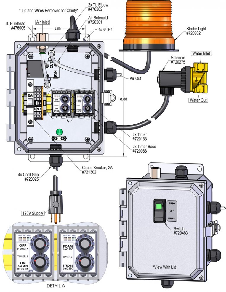
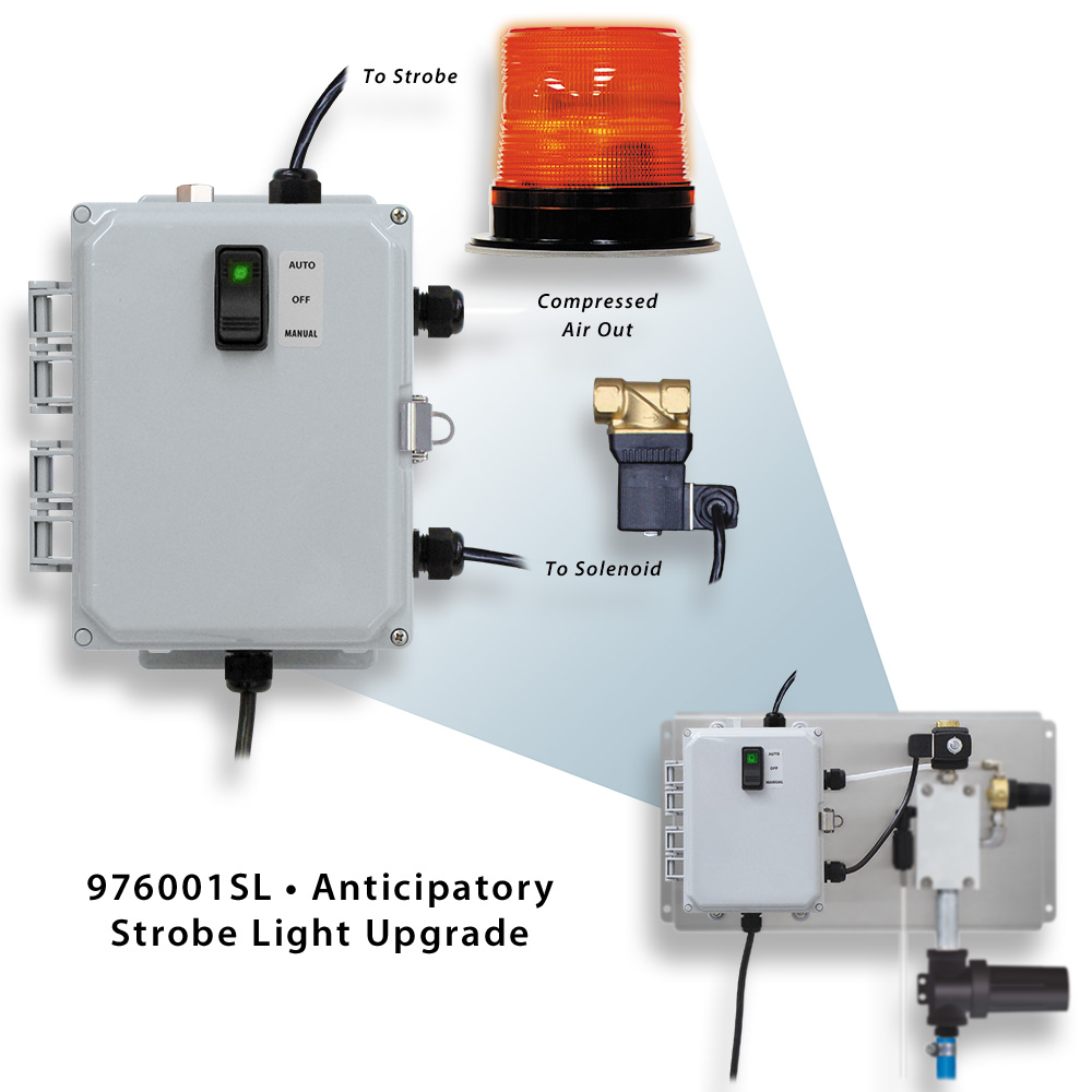
Model # 976001SL · Anticipatory Strobe Light Upgrade for Entryway Foam Sanitizers (Specify at Time of Purchase)

Requirements

Electric 120V
Entryway Foam Sanitizer 976500, 976505, 976530, or 976560
976001SL
Warning! Read All Instructions Before Using Equipment!

Overview

The Anticipatory Strobe Light Upgrade allows any Venturi Timed Entryway Foam Sanitizer to activate a strobe light and provide warning of foamer activation. The dual multi-function timers also control the minimum amount of time between activation, preventing costly over-application when traffic is heavy. Timer settings are field adjustable.  This upgrade must be specified at the time of purchase.

Safety & Operational Precautions

  • When connecting to a potable water supply follow all local codes for backflow prevention.
  • See Additional Safety Precautions included with the Electrical Control Box Installation Information
  • Always consider electrical shock hazard when working with and handling electrical equipment. If uncertain, consult an Electrician. Electrical wiring should only be done by a qualified Electrician.
  • For proper performance do NOT modify, substitute nozzle, hose diameter or electrical control box.
  • Manufacturer assumes no liability for the use or misuse of this unit.
  • Wear protective clothing, gloves and eye wear when working with chemicals.
  • Always direct the discharge away from people and electrical devices.
  • Follow the chemical manufacturer's safe handling instructions.
  • NEVER mix chemicals without first consulting chemical manufacturer.
  • Disconnect electrical power to the control box prior to opening it.
  • If the control box is connected to compressed air, the compressed air pressure should be kept to a maximum of 90 PSI.

To Install (refer to diagram on next page)

Illustration on Page 1 shows overall system setup.  Refer to companion instructions for control box upgrades.

  1. Install foam enhancer to entryway foamer discharge.  The arrow on the foam enhancer should point UP - opposite the flow direction.
  2. Mount the unit to a suitable surface above chemical supply to prevent siphoning.
  3. Connect the unit to the spreader nozzle using only the provided 10' hose, or extend the discharge using hose or piping that matches the ID of the provided hose (hose ID is very important). Use as few elbows as possible. Minimum length of the total hose/pipe between unit and nozzle is 10'.
  4. Mount the spreader nozzle slot several inches off the ground (refer to Page 1 illustration for details)
  5. Connect water and compressed air to the unit.

Set the chemical dilution ratio by threading one of the color coded metering tips into each chemical check valve. See chemical labels for dilution ratio recommendation or consult your chemical supplier.

  • For the strongest dilution ratio do NOT install a colored metering tip.
  • The dilution ratios in the metering tip chart are based on water thin chemicals with a viscosity of 1CPS.
  • Thicker chemicals will require a larger tip than the ratios shown in the chart.
  • Application results will ultimately determine final tip color.
  • Select the tip color that is closest to your desired chemical strength and thread it into the tip holder. DO NOT OVER-TIGHTEN.
  • Push the chemical tube over the check valve barb and place the suction tube in the chemical concentrate.
  • If necessary, cut suction tube(s) to length before attaching suction strainer.

To Operate

TO TEST

  1. Plug the power cord into 120 VAC outlet. GFI recommended.
  2. Open your water supply valve and your air supply valve, and then turn on the power switch. (See Timer Adjustment and Switch Settings below.)
  3. Final chemical dilution and air adjustments will now have to be made.
  4. Wait a few seconds and observe foam consistency.
    • Use the least amount of air needed to achieve good foam quality to prevent water pressure fluctuations from affecting performance. Air pressure must be kept lower than water pressure.
    • To adjust foam consistency pull out on the air regulator knob, turn slightly clockwise for dryer foam and counterclockwise for wetter foam. Wait a few seconds to see each adjustment.
    • You may also have to try different sized metering tips and air settings until foam consistency is acceptable. Once this is set and desired foam consistency is achieved push lock the knob. You are ready to start.

TIMER ADJUSTMENT

  1. CAUTION! UNPLUG THE POWER CORD before removing control box cover. The box contains two dual function timers that work in tandem
  2. Set each timer dial by turning the knob to point the red arrow to the desired set point. DO NOT turn the dial past zero to the left or past 6 to the right.
    • The ON TIME dial controls the overall operation of the unit and should be set to 2 minutes.
    • The OFF TIME dial controls how long the unit will stay off (0 to 60 minutes) between foam applications, adjustable in 2-minute increments.
    • The STROBE and FOAM timers are set the same way (0 to 60 seconds), adjustable in 2-second increments. When activated, the strobe will begin first and foaming begins when the strobe stops. 
  3. Replace the control box cover and follow the TO TEST instructions above.

SWITCH SETTINGS (on front of Control Box)

  • Automatic control – Top of switch is depressed. Green light glows.
  • OFF – Switch is in middle position; green light is off
  • Manual control – Press bottom of switch. Unit is active only while switch is pressed. When released, the switch returns to the OFF position.
  • Note: The unit will run 24 hours a day unless the power switch is manually turned off.
976001SL.jpg
Troubleshooting Guide
Problem Possible Cause / Solution
StartupMaintenance
A) Foamer will not draw chemical.
B) Foam surges.
C) Foam output too wet.
D) Foam output too dry.
E) Doesn't come on when switch is turned on.
F) Comes on and runs continuously.
G) Comes on but no water through solenoid.
H) Air or solution backing up into water line.
1, 7, 8, 9, 10
1, 2, 3, 4, 6, 7, 8, 9, 10
2, 3, 4, 6, 7, 8, 9, 10
1, 5
11,12
11
10
13, 14, 15, 16, 17, 19, 20
13, 14, 15, 16, 17, 19, 20
13, 14, 15, 16, 17, 18, 19, 20
17


19
21
Possible Cause / Solution
StartupMaintenance
  1. Air pressure too high
    • Adjust air regulator slowly counterclockwise until output stabilizes.
  2. Air adjustment too low
    • Adjust air regulator very slowly clockwise.
  3. Use of an oiler in the airline will cause poor foam quality
    • Use only clean, dry air.
  4. Not enough chemical - metering tip too small
    • Install larger metering tip.
  5. No metering tip installed or metering tip too large
    • Install smaller metering tip.
  6. Improper chemical
    • Ensure product is recommended for foaming and/or the application.
  7. Chemical tube not immersed in chemical or chemical depleted
    • Immerse tube or replenish
  8. Foam hose kinked or hose/plumbing too short or wrong size
    • (See REQUIREMENTS on page 1)
  9. Water pressure too low or water volume too low/inlet piping too small
    • Increase water pressure or water volume. (See REQUIREMENTS on page 1)
  10. No water to the unit
    • Ensure that the water supply is not shut off to the unit.
  11. Timer failed/Controller not set properly or malfunctioned
    • Replace timer. See Controller manual.
  12. May have electrical problems
    • Ensure circuit breaker (5 Amp) has not been tripped.
    • Have a qualified electrician check electrical connections.
  1. Chemical check valve stuck or failed
    • Clean or replace.
  2. Chemical strainer or metering tip partially blocked
    • Clean or replace chemical strainer and/or metering tip.
  3. Chemical tube stretched out where tube slides over check valve or pin hole/cut in chemical tube (sucking air in)
    • Cut off end of tube or replace tube.
  4. Vacuum leak in chemical pick-up connections
    • Tighten the connections.
  5. Air regulator failed allowing too much air or not enough air
    • Clean or replace.
  6. Air check valve or air solenoid clogged or failed
    • Clean or replace.
  7. Water solenoid clogged or failed
    • Clean or replace the water solenoid.
  8. Chemical build-up may have formed in the body, causing poor or no chemical pick-up
    • Follow PREVENTIVE MAINTENANCE instructions below, using hot water or descaling acid. When there is no draw at all, carefully remove fittings and soak entire body in descaling acid.
  9. No backflow preventer installed
    • Install appropriate backflow preventer into water line.
PREVENTIVE MAINTENANCE: When the unit will be out of service for extended periods, place chemical tube(s) in water and flush the chemical out of the unit to help prevent chemical from drying out and causing build-up. Periodically check and clean chemical strainer and replace if missing.