Lafferty Equipment Manufacturing, LLC

Installation & Operation Instructions

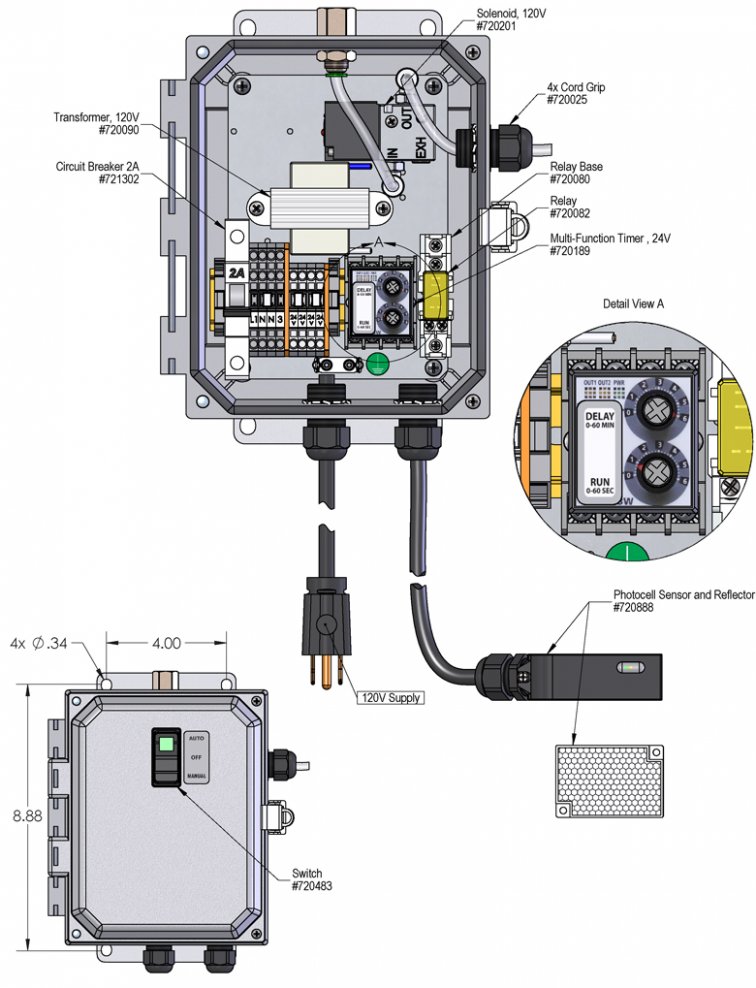
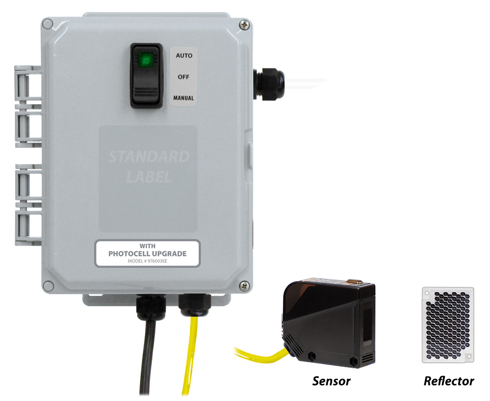
Model # 976003EE · Photocell Upgrade for Pump Fed Entryway Foam Sanitizers (Specify at Time of Purchase)

Requirements

Electric 120V
Entryway Foam Sanitizer 976250, 976256, or 976260
976003EE
Warning! Read All Instructions Before Using Equipment!

Overview

The Photocell Upgrade allows any Pump Fed Timed Entryway Foam Sanitizer to be activated "on-demand" via a photocell sensor and apply foam to the entryway floor for a set amount of time. The multi-function timer also controls the minimum amount of time between activation, preventing costly over-application when traffic is heavy. Timer settings are field adjustable.  This upgrade must be specified at the time of purchase.

Safety & Operational Precautions

  • See Additional Safety Precautions included with the Electrical Control Box Installation Information
  • Always consider electrical shock hazard when working with and handling electrical equipment. If uncertain, consult an Electrician. Electrical wiring should only be done by a qualified Electrician, per Local and State Electrical Codes.
  • For proper performance do NOT modify, substitute nozzle, hose diameter or electrical control box.
  • Manufacturer assumes no liability for the use or misuse of this unit.
  • Wear protective clothing, gloves and eye wear when working with chemicals.
  • Always direct the discharge away from people and electrical devices.
  • Follow the chemical manufacturer's safe handling instructions.
  • NEVER mix chemicals without first consulting chemical manufacturer.
  • Disconnect electrical power to the control box prior to opening it.

To Install (refer to diagram on next page)

Refer to companion instructions for Entryway Foamer installation instructions (plumbing, initial setup, etc.)

  1. Mount and align the photocell sensor and reflector on either side of the entryway.
  2. They will need to be mounted far enough in front of the door to allow time for the foam to be dispensed onto the floor, prior to the person or vehicle passing through the entryway. Actual distances will vary, depending upon the plumbing used and the timer setting.

To Operate

TO TEST

  1. Plug the power cord into 120VAC outlet.
  2. Open your solution supply valve and your air supply valve, and then turn on the power switch. Push and hold down the switch on the box that is labeled "Manual".
  3. The unit will activate so you can see how long it takes the foam to travel through your plumbing and foam the entryway. Final adjustments can now be made to the positioning of the photocell sensor and reflector.
  4. Final air adjustments will now have to be made.
  5. Wait a few seconds and observe foam consistency.
    • Use the least amount of air needed to achieve good foam quality to prevent solution pressure fluctuations from affecting performance. Air pressure must be kept lower than solution pressure.
    • To adjust foam consistency pull out on the air regulator knob, turn slightly clockwise for drier foam and counterclockwise for wetter foam. Wait a few seconds to see each adjustment.
    • Once desired foam consistency is achieved push lock the knob. You are ready to start.

TIMER ADJUSTMENT

  1. Make sure the system is not plugged in to a power source. Remove control box cover. The box contains one timer with "Run & Delay" adjustment knobs.
    Run: The length of time the unit runs each time the photocell beam is broken. Turn the knob to set the run time (0-60 Seconds). Generally 8-10 seconds will provide sufficient foam.
    Delay: The length of time the unit is inactive after each application. Turn the knob to set the delay time (0-60 Minutes). Generally the foam will be good for 10-15 minutes.
  2. Replace the control box cover and connect the unit to a 120V power source.
  3. The unit is ready for operation. The run mode will activate the unit for the preset time and then time out. It will not reactivate until the time runs out on the delay mode.
    Note: The unit will run 24 hours a day unless the power switch is manually turned off.
    For extra foam at any time, use the Manual function (See Switch Settings, below.)
SWITCH SETTINGS (on front of Control Box)
  • Automatic control – Top of switch is depressed. Green light glows.
  • OFF – Switch is in middle position; green light is off
  • Manual – Press and hold bottom of switch to activate manual foaming
976003EE.jpg
Troubleshooting Guide
Problem Possible Cause / Solution
StartupMaintenance
A) Foam surges.
B) Foam output too wet.
C) Foam output too dry.
D) Unit doesn't come on when switch is turned on.
E) Unit comes on and runs continuously.
F) Unit comes on but no solution through solenoid.
1, 2, 3, 4, 6, 7, 8, 9, 10, 11
2, 3, 4, 6, 7, 8, 9, 10, 11
1, 5
11, 12, 13
12
14, 16, 17
14, 15, 16, 17
14, 15


16
Possible Cause / Solution
StartupMaintenance
  1. Air pressure too high
    • Adjust air regulator slowly counterclockwise until output stabilizes.
  2. Air adjustment too low
    • Adjust air regulator very slowly clockwise.
  3. Use of an oiler in the airline will cause poor foam quality
    • Use only clean, dry air.
  4. Not enough chemical
    • Increase chemical concentration.
  5. Too much chemical
    • Decrease chemical concentration.
  6. Improper chemical
    • Ensure product is recommended for foaming and/or the application.
  7. Foam hose kinked or hose/plumbing too long or wrong size (See REQUIREMENTS)
    • Straighten the hose.
  8. Nozzle size too small (See REQUIREMENTS)
  9. Chemical solution pressure too low or volume too low / inlet piping too small
    • Increase solution pressure or volume (See REQUIREMENTS).
  10. No chemical solution to the unit
    • Ensure that the chemical solution supply is not shut off to the unit.
  11. Photocell sensor and receiver not aligned or malfunctioned
    • Align sensor and receiver
      Consult sensor/receiver instruction manual
  12. Timer failed/Controller not set properly or malfunctioned
    • Replace timer. See Controller manual.
  13. May have electrical problems
    • Have a qualified electrician check electrical connections. Ensure circuit breaker (2 amp) has not been tripped at control box.
  1. Air regulator failed allowing too much air or not enough air
    • Clean or replace.
  2. Air check valve or air solenoid clogged or failed
    • Clean or replace.
  3. Chemical solution solenoid clogged or failed
    • Clean or replace.
  4. Chemical build-up may have formed in the body, causing poor or no chemical pick-up
    • Follow PREVENTIVE MAINTENANCE instructions below, using water. In extreme cases, carefully remove fittings and soak entire body in descaling acid.
PREVENTIVE MAINTENANCE: When the unit will be out of service for extended periods, place chemical tube(s) in water and flush the chemical out of the unit to help prevent chemical from drying out and causing build-up. Periodically check and clean chemical strainer and replace if missing.