Lafferty Equipment Manufacturing, LLC

Installation & Operation Instructions

Model # 976490 · Timed Entryway Airless Foam Sanitizer

Requirements

Chemical Concentrate
Water
Temperature up to 160°F
Pressure 35 to 125 PSI
Flow 1.34 GPM @ 40 PSI
Supply Line 1/2"
Hose 1/2" ID x 10'
Nozzle A-25 Airless Foam Wand
Electric 120V

Options

Stainless Steel Jug Racks
1 Gallon Round/Square# 224200
1 Gallon Round/Square Locking# 224200-L
2 ½ Gallon (8 ½" x 10 ½")# 224210
5 Gallon Round/Square Locking (12" x 12")# 224214
5 Gallon Round/Square (12" x 12")# 224215
Alternate Chemical Check Valve - Viton Standard
Check Valve, Chemical, PP(W), 1/4" (EPDM)# 491401
976490
Warning! Read All Instructions Before Using Equipment!

Overview

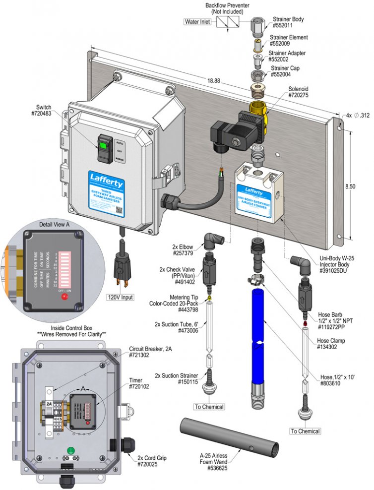
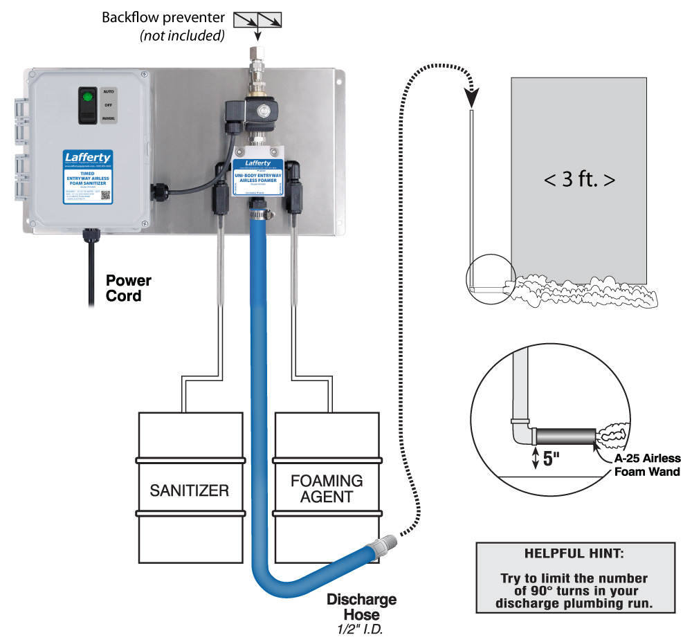
The Timed Entryway Airless Foam Sanitizer is an automated foam applicator for projecting sanitizing chemicals on to floors of 3' wide employee walk doors to prevent cross contamination, without compressed air. When activated, this venturi injection system uses city water pressure (35 - 125 PSI) to draw and blend chemical concentrate into the water stream to create an accurately diluted solution. The solution flows through the discharge hose to the airless foam wand which draws in atmospheric air to create wet, clinging foam. The system timer is user-programmable to meet the needs of any facility.

Safety & Operational Precautions

  • When connecting to a potable water supply follow all local codes for backflow prevention.
  • See Additional Safety Precautions included with the Electrical Control Box Installation Information
  • Always consider electrical shock hazard when working with and handling electrical equipment. If uncertain, consult an Electrician. Electrical wiring should only be done by a qualified Electrician.
  • For proper performance do NOT modify, substitute nozzle, hose diameter or electrical control box.
  • Manufacturer assumes no liability for the use or misuse of this unit.
  • Wear protective clothing, gloves and eye wear when working with chemicals.
  • Always direct the discharge away from people and electrical devices.
  • Follow the chemical manufacturer's safe handling instructions.
  • NEVER mix chemicals without first consulting chemical manufacturer.
  • Disconnect electrical power to the control box prior to opening it.
  • If the control box is connected to compressed air, the compressed air pressure should be kept to a maximum of 90 PSI.

To Install (refer to diagram on next page)

  1. Mount the unit to a suitable surface above chemical supply to prevent siphoning.
  2. Mount the airless foam wand about 5” off the floor at one side of the doorway. See Page 1 for proper installation layout.
  3. Connect the supplied 10’ section of 1/2" discharge hose to the foamer and connect it to the foam wand either directly or through 1/2" plumbing.
  4. Connect water to the unit.

NOTE: There WILL be dripping after each use as the pipe drains.

Set the chemical dilution ratio by threading one of the color coded metering tips into each chemical check valve. See chemical labels for dilution ratio recommendation or consult your chemical supplier.

  • For the strongest dilution ratio do NOT install a colored metering tip.
  • The dilution ratios in the metering tip chart are based on water thin chemicals with a viscosity of 1CPS.
  • Thicker chemicals will require a larger tip than the ratios shown in the chart.
  • Application results will ultimately determine final tip color.
  • Select the tip color that is closest to your desired chemical strength and thread it into the tip holder. DO NOT OVER-TIGHTEN.
  • Push the chemical tube over the check valve barb and place the suction tube in the chemical concentrate.
  • If necessary, cut suction tube(s) to length before attaching suction strainer.

To Operate

TO TEST

  1. Plug the power cord into 120 VAC outlet.
  2. The unit has been tested and the timer is preset to run for 60 seconds to allow for final adjustments. (ON TIME will activate first.) Open your water supply valve and then turn on the power switch.
  3. The unit will activate.
  4. Final chemical dilution adjustments will now have to be made.
  5. Wait a few seconds and observe foam consistency.
    • Depending upon available water pressure you may have to try different sized metering tips until foam consistency is acceptable.

TIMER ADJUSTMENT

  1. CAUTION! UNPLUG THE POWER CORD! Then open control box and adjust the timer. The ON TIME dip switches control how long the foam will be applied. The OFF TIME dip switches control how long the unit will stay off between foam applications. Add up the seconds for each activated dip switch to arrive at the desired duration of the ON cycle. Usually 10-15 seconds is sufficient to foam the floor. Add up the minutes for each activated dip switch to arrive at the desired duration of the OFF cycle. Set your OFF TIME to maintain the foam’s presence according to your flow (anywhere from 6 to 15 minutes).
  2. Close control box and plug in the power cord. Turn on the power switch. The unit will now function according to the timer settings. (ON TIME will activate first.)
  • Note: The unit will run 24 hours a day unless the power switch is manually turned off.
  • For extra foam at any time, press and hold the lower end (Momentary control) of the door switch. (See Switch Settings, below.)
SWITCH SETTINGS
  • Automatic control – Top of switch is depressed. Green light glows.
  • OFF – Switch is in middle position; green light is off
  • Momentary control – Press bottom of switch. Unit is active only while switch is pressed. When released, the switch returns to the OFF position.

Metering Tip Selection

Metering Tip Color
OZ/MIN
Dilution Ratio
@ 40 PSI
Brown
0.56306:1
Clear
0.88195:1
Bright Purple
1.38124:1
White
2.1580:1
Pink
2.9359:1
Corn Yellow
3.8445:1
Dark Green
4.8835:1
Orange
5.7730:1
Gray
6.0129:1
Light Green
7.0124:1
Med. Green
8.0621:1
Clear Pink
9.4318:1
Yellow Green
11.5015:1
Burgundy
11.9314:1
Pale Pink
13.8712:1
Light Blue
15.1411:1
Dark Purple
17.8810:1
Navy Blue
25.367:1
Clear Aqua
28.60
Black
50.00
No Tip Ratio Up To:6:1
The dilution ratios above are approximate values. Due to chemical viscosity, actual dilution ratios may vary.

Formula

GPM × 128 ÷ Desired Dilution Ratio = oz/min

  • See Unit Flow Rates chart for GPM
  • Use 20 for 20:1 dilution ratio, 30 for 30:1, etc.
  • Match calculated ounces per minute (oz/min) to nearest oz/min in Metering Tip Selection chart.

Unit Flow Rates

PSIGPM
351.25
401.34
501.50
601.64
701.77
801.90
902.01
1002.12
1102.22
1202.32
1252.37
976490.jpg
Troubleshooting Guide
Problem Possible Cause / Solution
StartupMaintenance
A) Unit will not draw chemical
B) Dilution too weak
C) Dilution too strong
D) Foam output too wet
E) Water backing up into chemical container
F) Doesn't come on when switch is turned on.
G) Comes on and runs continuously.
H) Solution backing up into water line
1, 5, 6, 7, 8
2, 5, 6
3
4

9, 10
9
11, 12, 13, 14, 15, 16, 17
11, 12, 13, 14, 15, 16

17
11
17, 18
18
19
Possible Cause / Solution
StartupMaintenance
  1. Inlet ball valve not completely open
    • Completely open ball valve.
  2. Not enough chemical - metering tip too small
    • Install larger metering tip.
  3. No metering tip installed or metering tip too large
    • Install smaller metering tip.
  4. Improper chemical/not enough chemical/not enough water pressure
    • Ensure product is recommended for foaming and/or the application
    • Install larger metering tip
    • Increase water pressure
  5. Chemical tube not immersed in chemical or chemical depleted
    • Immerse tube or replenish.
  6. Discharge hose too long for available water pressure, kinked or wrong size
    • Straighten the hose or replace hose.
  7.  ONLY use supplied foam wand (s)  (SEE REQUIREMENTS)
  8. Water pressure or water volume too low/inlet piping too small causing poor chemical pick up
    • Increase water pressure or water volume
  9. Timer failed/Controller not set properly or malfunctioned
    • Replace timer. See Controller manual.
  10. May have electrical problems
    • Ensure circuit breaker (5 Amp) has not been tripped.
    • Have a qualified electrician check electrical connections.
  1. Chemical check valve stuck or failed
    • Clean or replace.
  2. Chemical strainer or metering tip partially blocked
    • Clean or replace chemical strainer and/or metering tip.
  3. Chemical tube stretched out or pin hole/cut in chemical tube
    • Cut off end of tube or replace tube.
  4. Vacuum leak in chemical pick-up connections
    • Tighten the connection.
  5. Water strainer clogged or missing/injector inlet orifice clogged
    • Clean or replace strainer; check/clean inlet orifice for obstructions.  DO NOT DRILL OUT.
  6. Hard water scale or chemical build-up may have formed in the injector body causing poor or no chemical pick-up
    • Follow Preventive Maintenance instructions below, using hot water and/or de-scaling acid. When there is no draw at all, carefully remove fittings and soak entire injector body in de-scaling acid.
  7. Blockage in airless foam wand obstructing flow
    • Clean or replace
  8. Water solenoid clogged or failed
    • Clean or replace
  9. No back flow preventer installed
    • Install appropriate backflow preventer into the water line
PREVENTIVE MAINTENANCE: When the unit will be out of service for extended periods, place chemical tube(s) in water and flush the chemical out of the unit to help prevent chemical from drying out and causing build-up. Periodically check and clean chemical strainer and replace if missing.