Lafferty Equipment Manufacturing, LLC

Installation & Operation Instructions

Model # 977899 · 2-Way Magnetic AP-MT Asphalt Release Spray System

Requirements

Chemical Concentrate
Static Tank of Water
Compressed Air up to 10 CFM
Minimum Air Supply Line 3/8"
Hose 3/4" ID x 40'
Nozzle 45WSQ
Electric 120V

Options

Heater Assembly
Retro-Fit Heater Assembly# 720981
Drum & Tote Stick Lengths & Seal Materials
Drum Stick, 33" (Viton or EPDM)# 491643 / 491643-E
Drum Stick, 48" (Viton or EPDM)# 491648 / 491648-E
Drum Stick, 54" (Viton or EPDM)# 491645 / 491645-E
Tote Stick, 33" (Viton or EPDM)# 491653 / 491653-E
Tote Stick, 48" (Viton or EPDM)# 491654 / 491654-E
Tote Stick, 54" (Viton or EPDM)# 491656 / 491656-E
977899
Warning! Read All Instructions Before Using Equipment!

Overview

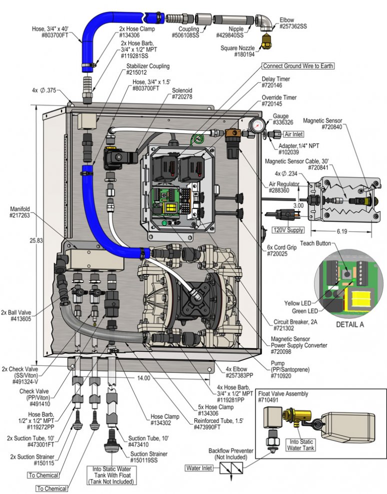
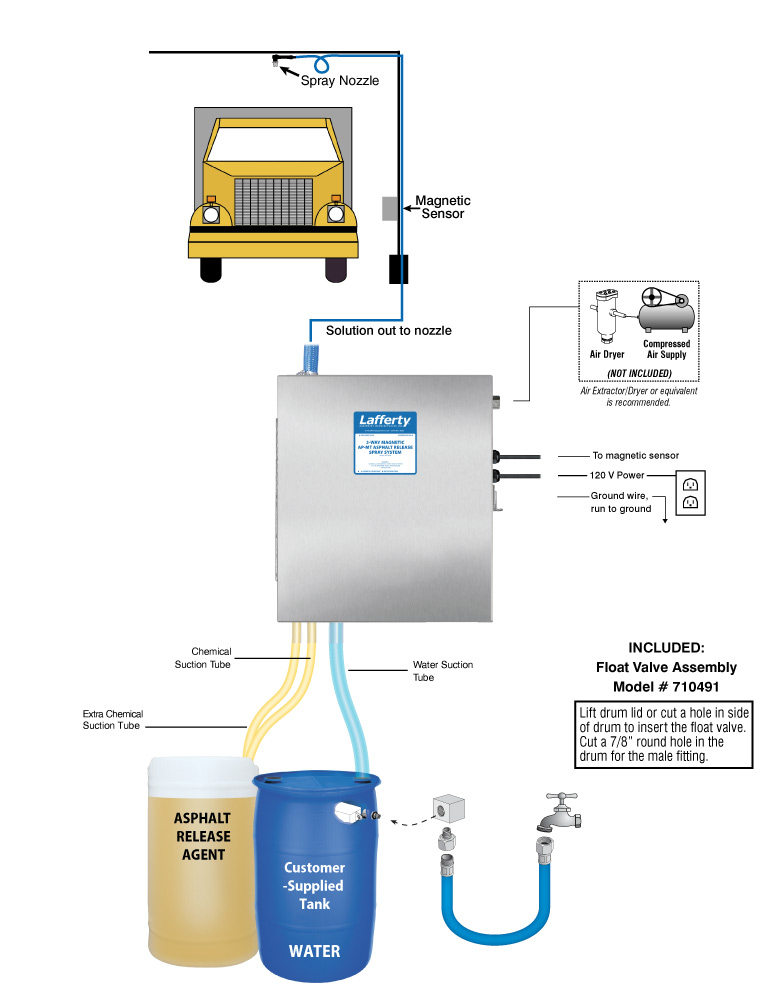
The 2-Way Magnetic AP-MT Asphalt Release Spray System is a magnetic sensor activated asphalt release sprayer for diluting chemical concentrate "on-the-fly" using metering tips and for coating any length asphalt truck bed with asphalt release agent. When a truck comes into range of the magnetic sensor, the system activates and a delay timer allows the driver to position the truck under the spray nozzle before applying release agent. When the vehicle leaves the spraying area, or time expires, the system shuts down and resets. Switch between different concentrations or chemicals with ball valves at the control box.

Safety & Operational Precautions

  • See Additional Safety Precautions included with the Electrical Control Box Installation Information
  • Always consider electrical shock hazard when working with and handling electrical equipment. If uncertain, consult an Electrician. Electrical wiring should only be done by a qualified Electrician, per Local and State Electrical Codes.
  • For proper performance do NOT modify, substitute nozzle, hose diameter or length
  • Manufacturer assumes no liability for the use or misuse of this unit.
  • Wear protective clothing, gloves and eye-wear when working with chemicals.
  • Always direct the discharge away from people and electrical devices.
  • Follow the chemical manufacturer’s safe handling instructions.
  • DO NOT use d-Limonene or other chemicals that are not compatible with the Santoprene diaphragms.
  • TEFLON upgrade is available.

To Install (refer to diagram on next page)

  1. Mount the unit to a solid, secure surface within 15' of the drive lane. Mount above chemical and water containers.
  2. Do NOT connect to electricity yet.
  3. Construct a mounting pole/arch, then mount the nozzle assembly as shown in the illustration on page 1. To prevent dripping after each cycle leave a loop in the hose to make the nozzle higher than the bottom of the loop.
  4. Mount Magnetic Sensor and perform set-up procedure. See separate Insert "Installation and Set-up Instructions for Magnetic Sensor"
  5. Install the supplied float valve assembly into your water tank as shown in the illustration on page 3. Attach your water supply hose to the float valve and turn on the water to fill the tank.
  6. Measure and cut the 1/4" suction tube into two sections of suitable length and connect them to the hose barbs as shown in the diagram on page 4. Both are for chemical concentrate and the dilution ratios will be set independently with metering tips after installation.
  7. Connect the 1/2" water suction tube to the hose barb. Secure all tubes with the clamps – do not over-tighten. Immerse ALL suction tubes into a container of water for initial testing.
  8. Connect your clean, dry compressed air supply to the system as shown in the illustration. (Air Extractor / Dryer is recommended.)
  9. Make sure the system is not plugged in to a power source. Remove control box cover. The box contains two timers (Delay & Override).
    Delay Timer: This timer allows you to set the time to the approximate number of seconds needed from the time the truck triggers the magnetic sensor until the truck bed is positioned underneath the nozzles. Set the timer by pushing the combination of dip switches that will equal the total number of seconds you need for the delay.
    Override Timer: This timer controls the maximum amount of time the sprayer will operate for. Set the timer by pushing the combination of dip switches that equal the total number of seconds you need the system to spray. Note: if the truck exits before this time has elapsed the spray will stop.
  10. Replace the control box cover.
  11. Plug the power cord into a 120 VAC power outlet. Activate your air supply.
TO TEST
  1. Perform "test runs" with water only and make any necessary timer adjustments, and any nozzle and magnetic sensor sensitivity adjustments.
  2. After several successful test runs have been made you are ready to set the chemical dilution.
  3. Immerse chemical suction tubes into the chemical container.
IF a ready-to-use chemical solution is being used place all three tubes in the solution.

Set the chemical dilution ratio by threading one of the color coded metering tips into each chemical check valve. See chemical labels for dilution ratio recommendation or consult your chemical supplier.

  • For the strongest dilution ratio do NOT install a colored metering tip.
  • The dilution ratios in the metering tip chart are based on water thin chemicals with a viscosity of 1CPS.
  • Thicker chemicals will require a larger tip than the ratios shown in the chart.
  • Application results will ultimately determine final tip color.
  • Select the tip color that is closest to your desired chemical strength and thread it into the tip holder. DO NOT OVER-TIGHTEN.
  • Push the chemical tube over the check valve barb and place the suction tube in the chemical concentrate.
  • If necessary, cut suction tube(s) to length before attaching suction strainer.

To Operate

Switch between dilution ratios (or chemicals) using the ball valves at the unit.  Activate only one ball valve at a time.

Once adjustments have been made to timers and chemical dilution:

  1. Drive the first truck through and make any last adjustments as needed.
  2. The unit is ready for operation.

Metering Tip Selection

Metering Tip Color
OZ/MIN
Dilution Ratio
@ 60 PSI
Brown
0.56914:1
Clear
0.88582:1
Bright Purple
1.38371:1
White
2.15238:1
Pink
2.93175:1
Corn Yellow
3.84133:1
Dark Green
4.88105:1
Orange
5.7789:1
Gray
6.0185:1
Light Green
7.0173:1
Med. Green
8.0664:1
Clear Pink
9.4354:1
Yellow Green
11.5045:1
Burgundy
11.9343:1
Pale Pink
13.8737:1
Light Blue
15.1434:1
Dark Purple
17.8829:1
Navy Blue
25.3620:1
Clear Aqua
28.6018:1
Black
50.0010:1
No Tip Ratio Up To:6.4:1
The dilution ratios above are approximate values. Due to chemical viscosity, actual dilution ratios may vary.

Formula

GPM × 128 ÷ Desired Dilution Ratio = oz/min

  • See Unit Flow Rates chart for GPM
  • Use 20 for 20:1 dilution ratio, 30 for 30:1, etc.
  • Match calculated ounces per minute (oz/min) to nearest oz/min in Metering Tip Selection chart.

Unit Flow Rates

PSIGPM
604.00
977899.jpg
Troubleshooting Guide
Problem Possible Cause / Solution
StartupMaintenance
A) Air pump will not run/pump.
B) Pump runs too fast with no output.
C) Unit will not draw chemical.
D) Water tube will not stay primed.
E) Chemical tube will not stay primed.
F) Unit comes on and runs continuously.
G) Asphalt continues to stick to truck.
1, 2, 3, 11, 12
1, 5, 7
5, 6, 7, 8, 9, 10, 11, 12
5, 7
7
11, 12
6, 8
13, 14, 17, 18, 19, 20
15, 16, 19
13, 14, 15, 16, 17, 18, 19, 20, 21
15, 16, 19
15, 16, 19
Possible Cause / Solution
StartupMaintenance
  1. Problem with air pump
    • Refer to pump manual.
  2. Use of an oiler in the airline will cause pump to stall
    • Use only clean, dry air.
  3. Inadequate air supply
    • Adjust air regulator slowly clockwise.
  4. Water knob not adequately opened
    • Turn water knob counterclockwise.
  5. Water tube(s) not immersed in water or water depleted
    • Immerse tube(s) or replenish.
  6. Chemical knob not adequately opened
    • Turn chemical knob counterclockwise.
  7. Chemical tube not immersed in chemical or chemical depleted
    • Immerse tube or replenish.
  8. Improper chemical
    • Ensure product is recommended for the application.
  9. Discharge hose wrong size or kinked (SEE REQUIREMENTS)
  10. Nozzle size too small (SEE REQUIREMENTS)
  11. Timer not set properly or malfunctioned
    • See Timer Adjustment on page 2 or replace timer.
  12. May have electrical problems
    • Have a qualified electrician check electrical connections. Ensure circuit breaker (5 amp) has not been tripped. Make sure magnetic sensor is functioning properly. If necessary, reset the background and sensitivity.
  1. Chemical check valve stuck or failed
    • Clean or replace.
  2. Chemical strainer blocked
    • Clean or replace chemical strainer.
  3. Chemical tube stretched out where tube slides over check valve or pin hole/cut in chemical tube (sucking air in)
    • Cut off end of tube or replace tube.
  4. Vacuum leak in chemical pick-up connections
    • Tighten the connections.
  5. Water check valve stuck or failed
    • Clean or replace.
  6. Water strainers blocked
    • Clean or replace chemical strainers.
  7. Water tubes stretched out where tube slides over check valve or pin hole/cut in water tubes (sucking air in)
    • Cut off end of tube or replace tube.
  8. Air regulator failed allowing too much air or not enough air
    • Clean or replace.
  9. Air solenoid clogged or failed
    • Clean or replace.
PREVENTIVE MAINTENANCE: When the unit will be out of service for extended periods, place chemical tube(s) in water and flush the chemical out of the unit to help prevent chemical from drying out and causing build-up. Periodically check and clean chemical strainer and replace if missing.