Lafferty Equipment Manufacturing, LLC

Installation & Operation Instructions

Model # 920205 · Pump Fed Foam / Foam Hose Drop Station

Requirements

Ready-to-Use Chemical Solution
Temperature up to 160°F
Pressure 35 to 125 PSI
Flow 1.7 GPM @ 40 PSI
Supply Line 1/2"
Compressed Air up to 3 CFM
Hose
Foam 3/4" ID x 50'
Foam 3/4" ID x 50'
Nozzle
Foam 50250
Foam 50250

Options

Stainless Steel Hose Racks
Large Stainless Steel Hose Rack# 224150
Foam Solution Check Valves & Strainer
Check Valve, PP, 1/2'' (EPDM)# 491409
Check Valve, PP, 1/2'' (Viton)# 491411
Check Valve, 316SS, 1/2", MF (Teflon)# 491348SS-T
Strainer, "Y", SS, 1/2" MF# 150350-1
Alternate Air Check Valve - EPDM Standard
Check Valve, Air, SS, 1/4" MM (Viton / Hast)# 491306
Stainless Steel Foam Wand (Upgrade)
Convert PP Wand to SS (New Units)# 536603-X
920205
Warning! Read All Instructions Before Using Equipment!

Overview

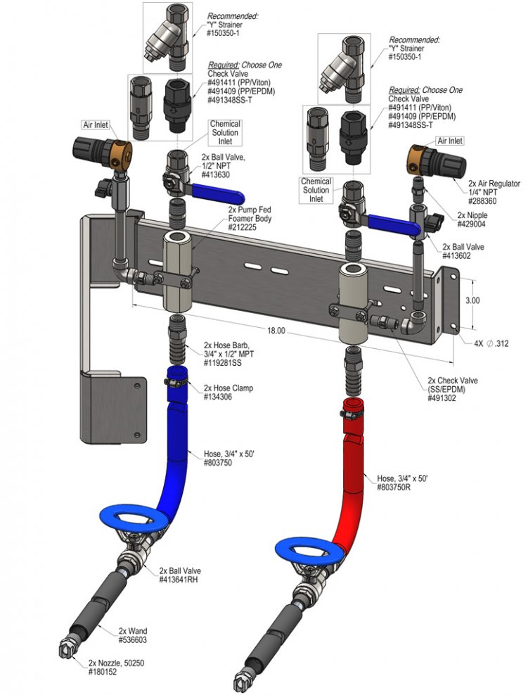
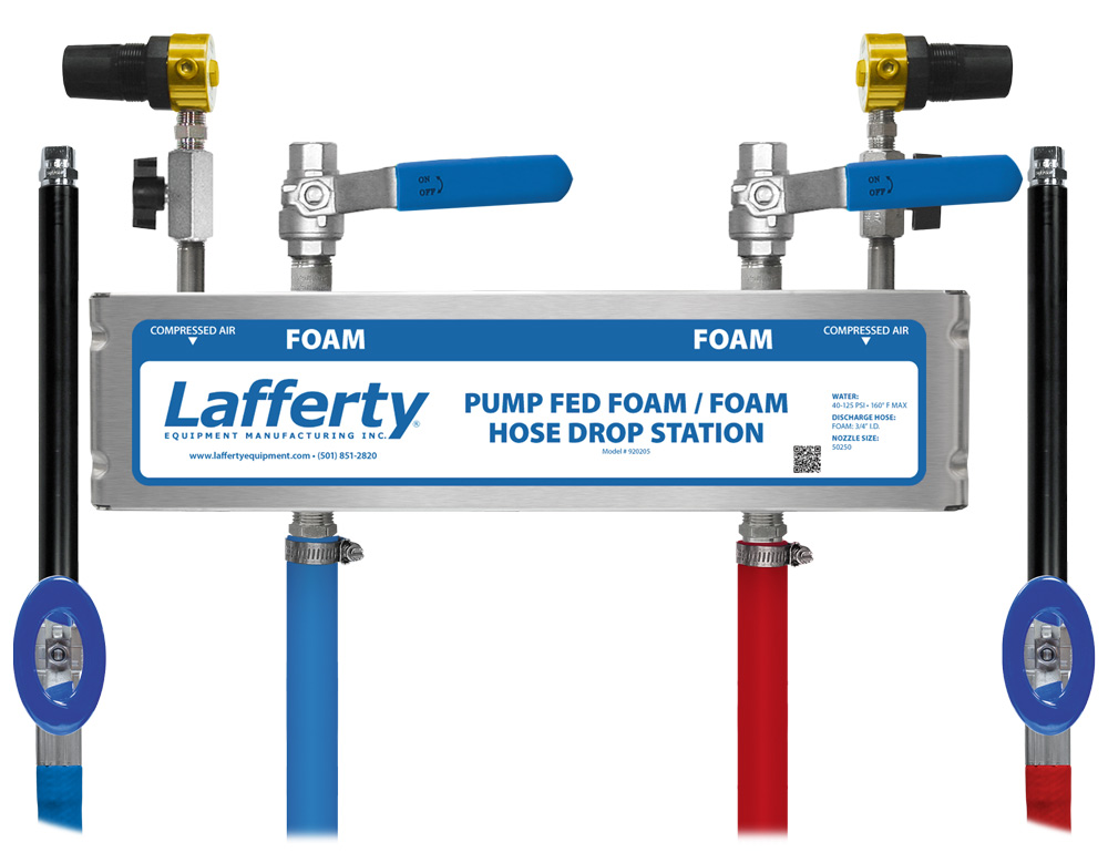
The Pump Fed Foam / Foam Hose Drop Station is a 2-way medium volume foam applicator for projecting 2 ready-to-use foaming chemicals. This unit receives 2 separate ready-to-use chemical solutions from separate central chemical feed systems and creates rich, clinging foam by injecting compressed air into the solutions to greatly increase volume and coverage ability. The foam is then projected through the dedicated discharge hoses and fan nozzles on to any surfaces up close or at distances up to 12 feet.

Safety & Operational Precautions

  • For proper performance do NOT modify, substitute nozzle, hose diameter or length.
  • Manufacturer assumes no liability for the use or misuse of this unit.
  • Wear protective clothing, gloves and eye-wear when working with chemicals.
  • Always direct the discharge away from people and electrical devices.
  • For pressures over 100 PSI, remove the discharge valve or lower pressure
  • Follow the chemical manufacturer’s safe handling instructions.
  • Turn off solution supply and air when unit is not in use for extended periods.

To Install (refer to diagram on next page)

A check valve is required on the foamer solution inlet to prevent air from going back into the solution line. (See Options)

  1. Mount the unit to a suitable surface.
  2. Connect the discharge hose as shown in the diagram and close the ball valve.
  3. Install a solution check valve on the foamer solution inlet and connect pre-mixed solution supply.
  4. To prevent blocking the small jets flush any new plumbing of debris before connecting. And/or install a strainer. (see options)
  5. Connect compressed air supply. If piping is older and has known contaminants, install a filter.

To Operate

  1. With wand in hand open the inlet ball valve, and the air ball valve.
    • Wait a few seconds and observe foam consistency.
    • Use the least amount of air needed to achieve good foam quality to prevent solution  pressure fluctuations from affecting performance. Air pressure must be kept lower than solution pressure.
    • To adjust the foam consistency pull out on the air regulator knob, turn slightly clockwise for dryer foam and counterclockwise for wetter foam. Wait a few seconds to see each adjustment.
    • Medium wet foam will give the best cleaning results! Dry foam will NOT clean as well!
    • You may also have to try different chemical ratios and air settings until foam consistency and cleaning results are acceptable. Once this is set and desired foam consistency is achieved push lock the knob. you are ready to start application.
  2. When foaming is completed, close the discharge ball valve, return to the unit and close the solution and air ball valves. Briefly re-open the discharge ball valve to relieve pressure in the hose. Rinse before the foam dries.

Unit Flow Rates

PSIGPM
FoamFoam
351.591.59
401.701.70
501.901.90
602.082.08
702.252.25
802.402.40
902.552.55
1002.692.69
1102.822.82
1202.942.94
1253.013.01
920205.jpg
Troubleshooting Guide
Problem Possible Cause / Solution
StartupMaintenance
A) Foam surges and/or hose "bucks".
B) Foam too wet.
C) Foam does not clean properly or too dry.
D) Chemical solution backing up into air line.
1, 2, 3, 4, 5, 6, 7, 8
2, 3, 4, 5, 6
1, 4, 9
11
10, 12, 13
10, 12, 13
10
Possible Cause / Solution
StartupMaintenance
  1. Air pressure too high
    • Adjust the air regulator slowly counterclockwise until output stabilizes.
  2. Use of an oiler in the airline will cause poor foam quality
    • Use only clean, dry air.
  3. Inlet ball valve or discharge ball valve not completely open
    • Completely open the inlet and discharge ball valves.
  4. Improper chemical or solution too weak
    • ​​​​​​​Ensure product is recommended for foaming and/or the application. Increase chemical concentration.
  5. Discharge hose too long, wrong size, kinked or spliced/​​​​​​​sectioned together (SEE REQUIREMENTS)
    • ​​​​​​​Straighten the hose - Replace hose with correct size or one piece continuous hose.
  6. Nozzle size is wrong (SEE REQUIREMENTS)
  7. ​​​​​​​Solution pressure or volume too low/inlet piping too small
    • ​​​​​​​Increase solution pressure or volume (SEE REQUIREMENTS).
  8. Air backing up into solution line
    • ​​​​​​​Install optional solution check valve (see OPTIONS, page 1).
  9. Soil has hardened on surface; always rinse foam before it dries
    • ​​​​​​​Reapplication may be necessary.
  1. Air regulator failed allowing too much air or not enough air
    • Clean or replace.
  2. Air check valve failed
    • ​​​​​​​Replace.
  3. Inlet orifice clogged
    • ​​​​​​​Check/clean inlet orifice for obstructions. DO NOT DRILL OUT. Install optional solution "Y" strainer (see OPTIONS, page 1).
  4. Chemical build-up may have formed in the body causing restriction
    • ​​​​​​​Carefully remove fittings and soak entire body in descaling acid.
PREVENTIVE MAINTENANCE: When the unit will be out of service for extended periods, run water through the system to flush the chemical and help prevent chemical build-up.