Lafferty Equipment Manufacturing, LLC

Installation & Operation Instructions

Model # 930110 · 1-Way AP-MT Solvent Sprayer

Requirements

Ready-to-Use Chemical Solution
Compressed Air up to 4 CFM
Hose 1/2" ID x 50'
Nozzle 2515

Options

Stainless Steel Hose Racks
Large Stainless Steel Hose Rack# 224150
Stainless Steel Jug Racks
Jug Rack, SS, 1 Gallon, Round/Square# 224200
Jug Rack, SS, 2 1/2 Gallon# 224210
Jug Rack, SS, 5 Gallon, Round/Square# 224215
Drum & Tote Stick Lengths & Seal Materials
Drum Stick, 33" (Viton or EPDM)# 491643 / 491643-E
Drum Stick, 48" (Viton or EPDM)# 491648 / 491648-E
Drum Stick, 54" (Viton or EPDM)# 491645 / 491645-E
Tote Stick, 33" (Viton or EPDM)# 491653 / 491653-E
Tote Stick, 48" (Viton or EPDM)# 491654 / 491654-E
Tote Stick, 54" (Viton or EPDM)# 491656 / 491656-E
Proportioning / Filling Options
1-Way Ball Valve SS Mixing Station (4 GPM)# 985100SS
930110
Warning! Read All Instructions Before Using Equipment!

Overview

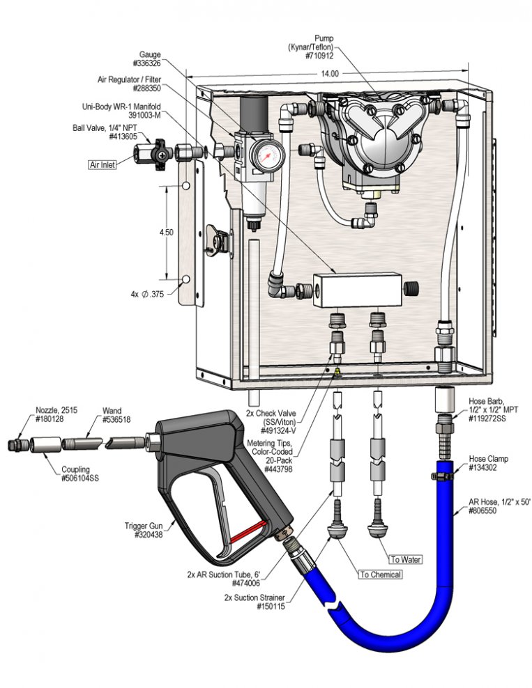
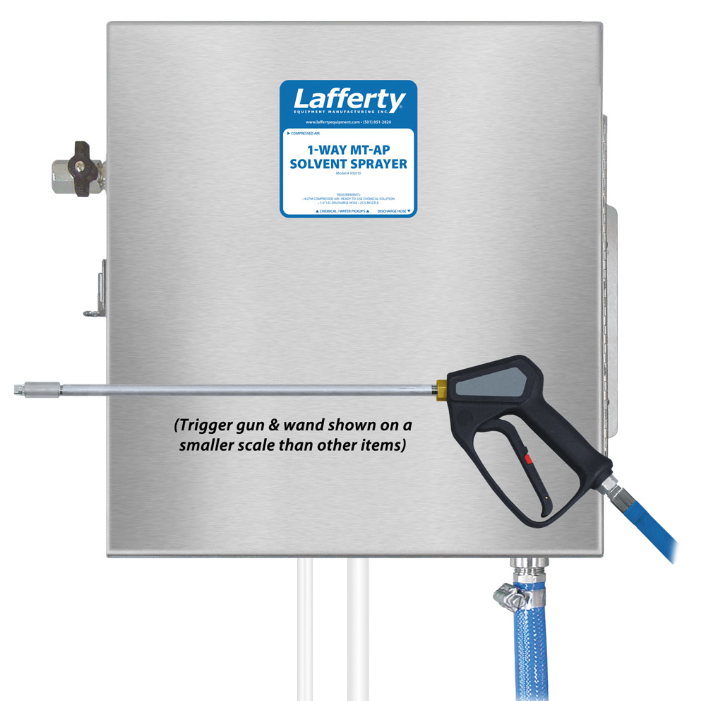
The 1-Way MT-AP Solvent Sprayer is a solvent spray applicator for either applying neat chemical or diluting "on-the-fly". This system is designed for facilities with low or no water pressure. It is suitable for handling many solvents (including d-limonene) and features a lockable, stainless steel enclosure. It uses a 3/8" Warren Rupp air-operated, double-diaphragm pump to draw either ready-to-use chemical from a static tank or a chemical concentrate and water from two tanks and blend them using precision metering tips. The solution is then projected through the discharge hose, trigger gun, wand and fan nozzle.

Safety & Operational Precautions

  • For proper performance do NOT modify, substitute nozzle, hose diameter or length
  • Manufacturer assumes no liability for the use or misuse of this unit.
  • Wear protective clothing, gloves and eye-wear when working with chemicals.
  • Always direct the discharge away from people and electrical devices.
  • Follow the chemical manufacturer’s safe handling instructions.
  • DO NOT use chemicals that are not compatible with glass filled polypropylene or the Teflon diaphragms.
  • Do not use products that contain sodium hypochlorite (bleach) or strong alkaline
  • Do NOT run the pump dry. This can cause damage to the pump.
  • Always slightly open the inlet ball valve until the pump primes.

To Install (refer to diagram on next page)

The unit has been tested and air pressure preset at the optimum setting of 60 PSI. Test "as is" before adjusting air pressure. Do not exceed 80 PSI.

  1. Mount the unit above chemical and water containers.
  2. Connect the discharge hose assembly.

    Note: If pre-diluted chemical solution is to be used, immerse both the chemical and water suction strainers in the chemical solution.

Set the chemical dilution ratio by threading one of the color coded metering tips into each chemical check valve. See chemical labels for dilution ratio recommendation or consult your chemical supplier.

  • For the strongest dilution ratio do NOT install a colored metering tip.
  • The dilution ratios in the metering tip chart are based on water thin chemicals with a viscosity of 1CPS.
  • Thicker chemicals will require a larger tip than the ratios shown in the chart.
  • Application results will ultimately determine final tip color.
  • Select the tip color that is closest to your desired chemical strength and thread it into the tip holder. DO NOT OVER-TIGHTEN.
  • Push the chemical tube over the check valve barb and place the suction tube in the chemical concentrate.
  • If necessary, cut suction tube(s) to length before attaching suction strainer.

To Operate

  1. Open the inlet air ball valve point the wand in a safe direction and pull the trigger on the gun.
  2. Final chemical dilution adjustments will now have to be made. Make adjustments to the metering tips based on results.
  3. Pull the trigger on the gun to begin application.
  4. When finished release the trigger, close the air ball valve and release pressure in the hose.

Metering Tip Selection

Metering Tip Color
Oz/Min
Dilution Ratio @ 60 PSI
Brown
0.56 456.1:1
Clear
0.88 289.9:1
Bright Purple
1.38 184.5:1
White
2.15 118.1:1
Pink
2.93 86.4:1
Corn Yellow
3.84 65.7:1
Dark Green
4.88 51.5:1
Orange
5.77 43.4:1
Gray
6.01 41.6:1
Light Green
7.01 35.5:1
Med. Green
8.06 30.8:1
Clear Pink
9.43 26.2:1
Yellow Green
11.50 21.3:1
Burgundy
11.93 20.5:1
Pale Pink
13.87 17.5:1
Light Blue
15.14 15.9:1
Dark Purple
17.88 13.3:1
Navy Blue
25.36 9.1:1
Clear Aqua
28.60 8.0:1
Black
50.00 4.7:1
No Tip Ratio Up To: 1:1
The dilution ratios above are approximate values. Due to chemical viscosity, actual dilution ratios may vary.

Formula

GPM × 128 ÷ Desired Dilution Ratio = oz/min

  • See Unit Flow Rates chart for GPM
  • Use 20 for 20:1 dilution ratio, 30 for 30:1, etc.
  • Match calculated ounces per minute (oz/min) to nearest oz/min in Metering Tip Selection chart.
 

UNIT Flow Rates

PSI GPM
60 2.00
930110.jpg
Troubleshooting Guide
Problem Possible Cause / Solution
StartupMaintenance
A) Air pump will not run or pump solution.
B) Unit will not draw chemical or water.
C) Using too much chemical
D) Cleaning results unacceptable
E) Pump runs too fast with no output.
1,5
2,5
3
4
6,10,11
7,8,9,10


7,8,9,10
Possible Cause / Solution
StartupMaintenance
  1. Air adjustment too low
    • Open air ball valve fully. Adjust air regulator slowly clockwise. Optimum air pressure is 90 PSI.
  2. Water or chemical tube not immersed in container or container empty
    • Immerse tube or replenish.
  3. Dilution too strong
    • Use a smaller metering tip.
  4. Dilution too weak
    • Use a larger metering tip.
  5. Discharge hose kinked
    • Straighten the hose.
  1. Air regulator clogged or failed
    • Clean or replace.
  2. Water or chemical check valve stuck or clogged
    • Clean or replace.
  3. Chemical or water strainer clogged up
    • Clean or replace.
  4. Chemical or water tube stretched out where tube slides over hose barbs or pin hole/cut in tube sucking air.
    • Cut off end of tube or replace tube.
  5. Problem with air pump
    • Refer to air pump instruction manual
  6. Use of an oiler in the airline will cause pump to stall
    • Use only clean, dry air.
PREVENTIVE MAINTENANCE: When the unit will be out of service for extended periods, place chemical tube(s) in water and flush the chemical out of the unit to help prevent chemical from drying out and causing build-up. Periodically check and clean chemical strainer and replace if missing.