Lafferty Equipment Manufacturing, LLC

Installation & Operation Instructions

Model # 910930 · 3-Bar Truck Foam Arch

Requirements

Water
Temperature up to 160°F
Pressure 40 - 125 PSI
Flow 7.35 GPM @ 40 PSI (total)
2.45 GPM @ 40 PSI (per bar)
Hose/Pipe 1-1/2"
Compressed Air up to 12 CFM

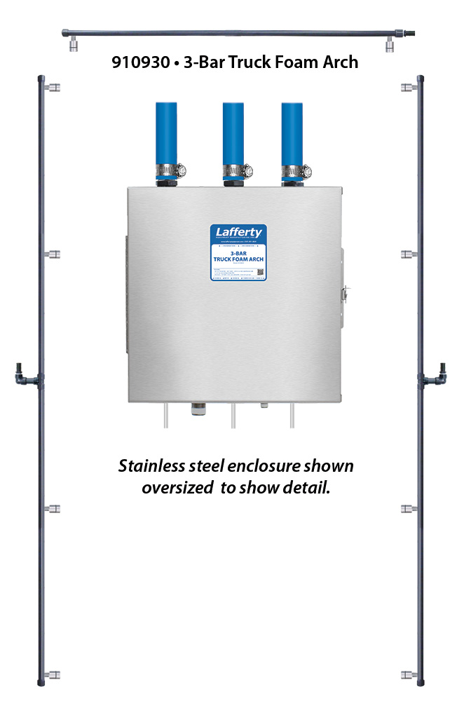
Side bar lengths and nozzle placement can be factory customized at the time of order

Options

Drum & Tote Stick Lengths & Seal Materials
Drum Stick, 33" (Viton or EPDM)# 491643 / 491643-E
Drum Stick, 48" (Viton or EPDM)# 491648 / 491648-E
Drum Stick, 54" (Viton or EPDM)# 491645 / 491645-E
Tote Stick, 33" (Viton or EPDM)# 491653 / 491653-E
Tote Stick, 48" (Viton or EPDM)# 491654 / 491654-E
Tote Stick, 54" (Viton or EPDM)# 491656 / 491656-E
Alternate Check Valve - Viton Standard
Check Valve, Chemical, PP, 1/2" HB (EPDM)# 491403
910930
Warning! Read All Instructions Before Using Equipment!

Overview

The 3-Bar Truck Foam Arch is a drive-through foam applicator for washing large vehicles and features 3 foam bar assemblies mounted above and and at the sides of the vehicle for complete coverage. This venturi injection unit uses city water pressure (40 - 125 PSI) to draw and blend chemical concentrate into the water stream to create accurately diluted solutions using precision metering tips. For optimal performance, water pressure should be 50 PSI or higher. Compressed air is injected to greatly increase volume and coverage ability, creating rich, clinging foam that is projected through multiple stainless steel Spreader Nozzles on each foam bar, which can be rotated for optimal coverage. The foam consistency (wet/dry) can be adjusted.

Safety & Operational Precautions

  • When connecting to a potable water supply follow all local codes for backflow prevention.
  • For proper performance do NOT modify, substitute nozzle, hose diameter or length.
  • Manufacturer assumes no liability for the use or misuse of this unit.
  • Wear protective clothing, gloves and eye wear when working with chemicals.
  • Always direct the discharge away from people and electrical devices.
  • Follow the chemical manufacturer's safe handling instructions.
  • NEVER mix chemicals without first consulting chemical manufacturer.

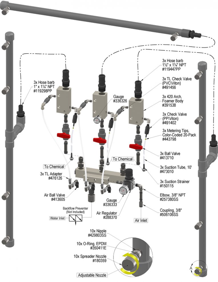
To Install (refer to diagram on next page)

If you are connecting to a potable water supply follow all local codes for backflow prevention.  

  • Bar lengths and nozzle placement are customized at the time of purchase. Call for details.
  1. Mount the unit to a suitable surface above the chemical supply to prevent siphoning.
  2. Assemble and glue the bars together making sure the nozzles line up straight.
  3. Firmly attach each bar to your support structure (not included)
  4. Connect a 1 1/2" discharge hose from the foamers to the bars as shown in the diagram. Or the bars can be hard plumbed using 1 1/2" pipe ONLY. Use at least 20' of hose or pipe in between the foamer and the bar to create good quality foam. Do not use too many elbows or other restrictions; They WILL hurt foam quality and overall performance. Use "sweeps" of hose, not elbows.
  5. Turn all ball valves to the off position. Connect 3/4" water supply. To prevent blocking the small water jets in the foamer flush any new plumbing of debris before connecting and /or install a water filter.
  6. Connect compressed air supply. If piping is older with known contaminants, install a filter.

Set the chemical dilution ratio by threading one of the color coded metering tips into each chemical check valve. See chemical labels for dilution ratio recommendation or consult your chemical supplier.

  • For the strongest dilution ratio do NOT install a colored metering tip.
  • The dilution ratios in the metering tip chart are based on water thin chemicals with a viscosity of 1CPS.
  • Thicker chemicals will require a larger tip than the ratios shown in the chart.
  • Application results will ultimately determine final tip color.
  • Select the tip color that is closest to your desired chemical strength and thread it into the tip holder. DO NOT OVER-TIGHTEN.
  • Push the chemical tube over the check valve barb and place the suction tube in the chemical concentrate.
  • If necessary, cut suction tube(s) to length before attaching suction strainer.

TO FOAM

Always make sure the foam bar is connected and pointed in a safe direction before turning water and air on. DO NOT kink the hose to stop foam flow, return to the unit and turn off water and air supplies

  1. Make final metering tip adjustments based on foam quality and cleaning results.
  2. With foam bar connected, activate water and air supplies.
  • Wait a few seconds and observe foam consistency.
  • Use the least amount of air needed to achieve good foam quality to prevent water pressure fluctuations from affecting performance. Air pressure must be kept lower than water pressure.
  • To adjust the foam consistency pull out on the air regulator knob, turn slightly clockwise for dryer foam and counterclockwise for wetter foam. Wait a few seconds to see each adjustment.
  • Medium wet foam will give the best cleaning results! Dry foam will NOT clean as well!
  • Once desired metering tip and foam consistency is achieved, push lock the knob. You are ready to start application.
  1. When foaming is completed close the water and air ball valves. Do NOT kink the hose to stop foam flow. Rinse the work surface before foam dries.

Metering Tip Selection

Metering Tip Color
OZ/MIN
Dilution Ratio
@ 40 PSI
Brown
0.56560:1
Clear
0.88356:1
Bright Purple
1.38227:1
White
2.15146:1
Pink
2.93107:1
Corn Yellow
3.8482:1
Dark Green
4.8864:1
Orange
5.7754:1
Gray
6.0152:1
Light Green
7.0145:1
Med. Green
8.0639:1
Clear Pink
9.4333:1
Yellow Green
11.5027:1
Burgundy
11.9326:1
Pale Pink
13.8723:1
Light Blue
15.1421:1
Dark Purple
17.8818:1
Navy Blue
25.3612:1
Clear Aqua
28.6011:1
Black
50.006:1
No Tip Ratio Up To:6:1
The dilution ratios above are approximate values. Due to chemical viscosity, actual dilution ratios may vary.

Formula

GPM × 128 ÷ Desired Dilution Ratio = oz/min

  • See Unit Flow Rates chart for GPM
  • Use 20 for 20:1 dilution ratio, 30 for 30:1, etc.
  • Match calculated ounces per minute (oz/min) to nearest oz/min in Metering Tip Selection chart.

Unit Flow Rates

PSIGPM
402.45
502.74
603.00
703.24
803.46
903.68
1003.87
1104.06
1204.24
1254.33
910930.jpg
Troubleshooting Guide
Problem Possible Cause / Solution
StartupMaintenance
A) Foam surges and/or hose "bucks".
B) Foamer will not draw chemical.
C) Foam too wet.
D) Foam does not clean properly (too dry).
E) Using too much chemical.
F) Water/chemical backing up into air line.
G) Water backing up into chemical container.
H) Air/chemical solution backing up into water line.
1, 2, 3, 4, 6, 7, 8, 9, 10
1, 3, 4, 7, 8, 9
2, 3, 4, 6, 7, 8, 9, 10
1, 4, 6, 11
5
12, 13, 14, 15, 16, 18, 19
12, 13, 14, 15, 16, 18, 19
13, 14, 15, 16, 18, 19


17
18
20
Possible Cause / Solution
StartupMaintenance
  1. Air pressure too high
    • Adjust the air regulator slowly counterclockwise until output stabilizes.
  2. Water pressure or water volume too low/inlet piping too small causing poor chemical pick up
    • Increase water pressure or water volume (SEE REQUIREMENTS).
  3. Inlet ball valve(s) not completely open
    • Completely open the inlet ball valves to ensure full flow
  4. Not enough chemical - metering tip too small
    • Install larger metering tip.
  5. No metering tip installed or metering tip too large
    • Install smaller metering tip.
  6. Improper chemical
    • Ensure product is recommended for foaming and the application.
  7. Chemical tube not immersed in chemical or depleted
    • Immerse tube or replenish.
  8. Discharge hose too long or wrong size or kinked
    • Straighten the hose or replace hose with correct size and length.
    • If a longer than the standard hose length provided is needed water pressure must be at or above 65 PSI for up to a 75' hose
  9. Nozzle flow rate(s) too low
    • Only use the provided number and size of nozzles.
  10. Use of an oiler in the airline will cause poor foam quality
    • Use only clean, dry air.
  11. Soil has hardened on surface, rinse foam before it dries
    • Reapplication may be necessary.
  1. Foamer inlet orifice clogged
    • Check/clean inlet orifice for obstructions. DO NOT DRILL OUT. Install a water filter.
  2. Chemical strainer or metering tip partially blocked
    • Clean or replace chemical strainer and/or metering tip.
  3. Chemical tube stretched out or pin hole/cut in chemical tube sucking air.
    • Cut off end of tube or replace tube.
  4. Vacuum leak in chemical pick-up connections
    • Tighten the connection.
  5. Air regulator failed allowing too much air or not enough air
    • Clean or replace.
  6. Air check valve failed - Discharge ball valve left closed with inlet ball valves open
    • Clean or replace.
  7. Chemical check valve stuck or failed
    • Clean or replace.
  8. Hard water scale or chemical build-up may have formed in the foamer body causing poor or no chemical pick-up
    • Follow Preventive Maintenance instructions below, using hot water or descaling acid. When there is no draw at all, carefully remove fittings and soak entire body in descaling acid.
  9. No backflow preventer installed and/or inlet ball valve left on when not in use
    • Install appropriate backflow preventer into water line.
PREVENTIVE MAINTENANCE: When the unit will be out of service for extended periods, place chemical tube(s) in water and flush the chemical out of the unit to help prevent chemical from drying out and causing build-up. Periodically check and clean chemical strainer and replace if missing.