Lafferty Equipment Manufacturing, LLC

Installation & Operation Instructions

Model # 917905HC · A-20SSHC Airless Foamer

Requirements

Chemical Concentrate
Water
Temperature up to 180°F
Pressure 400 to 1000 PSI
Flow 3.1 GPM @ 700 PSI
Supply Line 3/8"
Hose 3/8" ID x 50'
Nozzle A-40 Airless Foam Wand

Options

Stainless Steel Hose Racks
Large Stainless Steel Hose Rack# 224150
Stainless Steel Jug Racks
Jug Rack, SS, 1 Gallon, Round/Square# 224200
Jug Rack, SS, 2 1/2 Gallon# 224210
Jug Rack, SS, 5 Gallon, Round/Square# 224215
Safe Flow Lid™ for 1 Gallon Jugs
Lid, Suction Tube, and Strainer# 709101
Alternate Check Valve - EPDM Standard
Check Valve, Chemical, SS, Viton, 1/4"# 491324-V
917905HC
Warning! Read All Instructions Before Using Equipment!

Overview

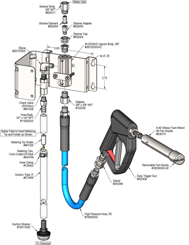
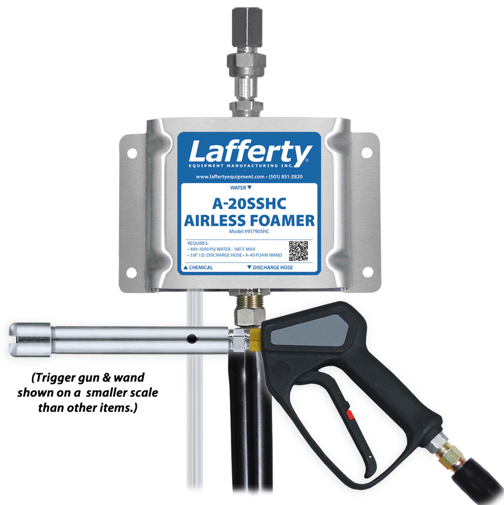
The A-20SSHC Airless Foamer is a 3.1 GPM @ 700 PSI "high concentrate" foam applicator that will produce strong dilution ratios for the toughest cleaning jobs without compressed air. This stainless steel venturi injection system uses high water pressure (400 - 1000 PSI) to draw and blend chemical concentrate into the water stream to create an accurately diluted solution. The solution then flows through the discharge hose and trigger gun to the "airless" foam wand which draws in atmospheric air to create and project wet, clinging foam at distances up to 12 feet.

Safety & Operational Precautions

  • For proper performance do NOT modify, substitute nozzle, hose diameter or length.
  • Manufacturer assumes no liability for the use or misuse of this unit.
  • Wear protective clothing, gloves and eye wear when working with chemicals.
  • Always direct the discharge away from people and electrical devices.
  • Follow the chemical manufacturer's safe handling instructions.

To Install (refer to diagram on next page)

If you are connecting to a potable water supply follow all local codes for backflow prevention.

  1. Mount the unit to a suitable surface above the chemical supply to prevent siphoning.
  2. Connect hose(s) as shown in the diagram.
  3. Flush any new plumbing of debris before connecting water.
  4. Connect water supply. Install a water filter if water piping is older or has known contaminants.

Set the chemical dilution ratio by installing the inline tip holder and a metering tip into chemical pick up tube. See chemical label for dilution ratio recommendation or consult your chemical supplier.

  • For the strongest possible chemical dilution ratio, do not install a metering tip.
  • The dilution ratios in the metering tip chart are based on chemical with a viscosity of 1CPS.
  • For water pressure other than the example, use the Metering Tip Selection Formula.
  • Due to varying chemical viscosity and applications, you may need to increase/decrease the tip size to get the best result.
  • Install a colored metering tip in the inline tip holder. DO NOT OVER-TIGHTEN
  • Splice tip holder into the chemical pick up tube as shown in the drawing. Use the hose clamp as shown in the diagram (certain units only). 
  • Once metering tip is installed immerse the chemical strainer into your chemical concentrate.
  • If necessary, cut suction tube(s) to length before attaching suction strainer.

To Operate

  1. Attach fan nozzle cap to foam wand discharge threads for wider output.  Remove fan nozzle cap to project zero degree stream.
  2. With trigger gun in hand, open the water supply.
  3. Pull the trigger and begin application.
  4. When application is completed, release the trigger then shut off the water supply.
  5. Briefly squeeze the trigger to relieve pressure in hose.
  6. Make final metering tip adjustments based on foam quality and cleaning results.

Metering Tip Selection

Metering Tip Color
OZ/MIN
Dilution Ratio
@ 700 PSI
Brown
0.56711:1
Clear
0.88452:1
Bright Purple
1.38288:1
White
2.15185:1
Pink
2.93136:1
Corn Yellow
3.84104:1
Dark Green
4.8882:1
Orange
5.7769:1
Gray
6.0166:1
Light Green
7.0157:1
Med. Green
8.0649:1
Clear Pink
9.4342:1
Yellow Green
11.5035:1
Burgundy
11.9333:1
Pale Pink
13.8729:1
Light Blue
15.1426:1
Dark Purple
17.8822:1
Navy Blue
25.3616:1
Clear Aqua
28.6014:1
Black
50.008:1
No Tip Ratio Up To:5:1
The dilution ratios above are approximate values. Due to chemical viscosity, actual dilution ratios may vary.

Formula

GPM × 128 ÷ Desired Dilution Ratio = oz/min

  • See Unit Flow Rates chart for GPM
  • Use 20 for 20:1 dilution ratio, 30 for 30:1, etc.
  • Match calculated ounces per minute (oz/min) to nearest oz/min in Metering Tip Selection chart.

Unit Flow Rates

PSIGPM
4002.35
5002.63
6002.88
7003.11
8003.32
9003.53
10003.72
917905HC.jpg
Troubleshooting Guide
Problem Possible Cause / Solution
StartupMaintenance
A) Unit will not draw chemical
B) Foam does not clean or foam properly
C) Using too much chemical
D) Water backing up into chemical container
1, 5, 6, 7
2, 4, 5, 7, 8
3
10, 11, 12, 13, 14
10, 11, 12, 13, 14

9
Possible Cause / Solution
StartupMaintenance
  1. Inlet ball valve not completely open
    • Completely open the ball valve.
  2. Not enough chemical - metering tip too small
    • Install larger metering tip.
  3. No metering tip installed or metering tip too large
    • Install smaller metering tip.
  4. Improper chemical
    • Ensure product is recommended for foaming and the application.
  5. Chemical tube not immersed in chemical or chemical depleted
    • Immerse tube or replenish.
  6. Discharge hose too long or wrong size (SEE REQUIREMENTS)
    • Replace hose with correct size/length.
  7. Water pressure or water volume too low/inlet piping too small causing poor chemical pick up
    • Increase water pressure or water volume (SEE REQUIREMENTS).
  8. Soil has hardened on surface; always rinse before it dries
    • Reapplication may be necessary.
  1. Chemical check valve stuck or failed 
    • Clean/disassemble and turn seat over or order rebuild kit.
  2. Chemical strainer or metering tip partially blocked 
    • Clean or replace chemical strainer and/or metering tip.
  3. Chemical tube stretched out or pin hole/cut in chemical tube (sucking air in) 
    • Cut off end of tube or replace tube.
  4. Vacuum leak in chemical pick-up connections 
    • Tighten the connection.
  5. Water strainer clogged or missing/injector inlet orifice clogged
    • Clean or replace strainer; check/clean inlet orifice for obstructions.  DO NOT DRILL OUT.
  6. Hard water scale or chemical build-up may have formed in the injector body or foam wand causing poor or no chemical pick-up
    • Follow Preventive Maintenance instructions below, using hot water and/or de-scaling acid. When there is no draw at all, carefully remove fittings and soak entire injector body and/or foam wand in de-scaling acid.
PREVENTIVE MAINTENANCE: When the unit will be out of service for extended periods, place chemical tube(s) in water and flush the chemical out of the unit to help prevent chemical from drying out and causing build-up. Periodically check and clean chemical strainer and replace if missing.