| Chemical Concentrate |
| Water | |
| Temperature | up to 180°F |
| Pressure | 25-125 PSI |
| Supply Line | 1/2" Minimum |
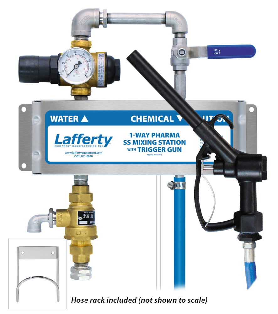
| Discharge Hose | 1/2" ID x 20' & Trigger Gun |
| Flow | |
| High Flow | 4.0 GPM @ 40 PSI |
| Low Flow | 1.95 GPM @ 40 PSI |
Requirements
| Chemical Concentrate |
| Water | |
| Temperature | up to 180°F |
| Pressure | 25-125 PSI |
| Supply Line | 1/2" Minimum |
| Discharge Hose | 1/2" ID x 20' & Trigger Gun |
| Flow | |
| High Flow | 4.0 GPM @ 40 PSI |
| Low Flow | 1.95 GPM @ 40 PSI |
Overview
Safety & Operational Precautions
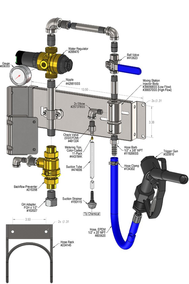
To Install (refer to diagram on next page)
If you are connecting to a potable water supply follow all local codes for backflow prevention.
TO SET DILUTION RATIO, thread a color-coded metering tip into each tip holder. See chemical labels for dilution ratio recommendation or consult your chemical supplier.
If a leaner solution than the maximum shown in the chart is required, it will be necessary to use one proportioner to pre-dilute the concentrate, and a second to dilute the resulting solution to the required final ratio. If this Double Dilution procedure is required, choose two metering tips whose ratios, when multiplied together, result in a ratio that is as close as possible to the required final ratio. Example: For two "Bottle Fill" Mixing Station valves with 40 PSI water pressure, use a White Tip (37:1) and a Corn Yellow Tip (21:1) to achieve a final solution ratio of 777:1.
With the adjustable pressure regulator it is possible to "dial in" and achieve a specific dilution ratio.
To Operate
Metering Tip Selection | |||
|---|---|---|---|
Metering Tip Color |
OZ/MIN |
Dilution Ratio | |
| High Flow | Low Flow | ||
Brown | 0.56 | 914:1 | 446:1 |
Clear | 0.88 | 582:1 | 284:1 |
Bright Purple | 1.38 | 371:1 | 181:1 |
White | 2.15 | 238:1 | 116:1 |
Pink | 2.93 | 175:1 | 85:1 |
Corn Yellow | 3.84 | 133:1 | 65:1 |
Dark Green | 4.88 | 105:1 | 51:1 |
Orange | 5.77 | 89:1 | 43:1 |
Gray | 6.01 | 85:1 | 42:1 |
Light Green | 7.01 | 73:1 | 36:1 |
Med. Green | 8.06 | 64:1 | 31:1 |
Clear Pink | 9.43 | 54:1 | 26:1 |
Yellow Green | 11.50 | 45:1 | 22:1 |
Burgundy | 11.93 | 43:1 | 21:1 |
Pale Pink | 13.87 | 37:1 | 18:1 |
Light Blue | 15.14 | 34:1 | 16:1 |
Dark Purple | 17.88 | 29:1 | 14:1 |
Navy Blue | 25.36 | 20:1 | 10:1 |
Clear Aqua | 28.60 | 18:1 | 9:1 |
Black | 50.00 | 10:1 | 5:1 |
| No Tip Ratio Up To: | 9:1 | 4:1 | |
| The dilution ratios above are approximate values. Due to chemical viscosity, actual dilution ratios may vary. | |||
Formula | |||
|
GPM × 128 ÷ Desired Dilution Ratio = oz/min
| |||
Unit Flow Rates | ||
|---|---|---|
| PSI | GPM | |
| High Flow | Low Flow | |
| 35 | 3.74 | 1.82 |
| 40 | 4.00 | 1.95 |
| 50 | 4.47 | 2.18 |
| 60 | 4.90 | 2.39 |
| 70 | 5.29 | 2.58 |
| 80 | 5.66 | 2.76 |
| 90 | 6.00 | 2.93 |
| 100 | 6.32 | 3.08 |
| 110 | 6.63 | 3.23 |
| 120 | 6.93 | 3.38 |
| 125 | 7.07 | 3.45 |
Troubleshooting Guide |
|---|
| Problem | Possible Cause / Solution | |
|---|---|---|
| Startup | Maintenance | |
| A) Unit will not draw chemical. B) Dilution too weak. C) Dilution too strong D) Water backing up into chemical container. E) Backflow preventer constantly dripping / leaking. | 1, 2, 3 4 5 |
6, 7, 8, 9, 10, 11 11 8 12 |
| Possible Cause / Solution | |
|---|---|
| Startup | Maintenance |
|
|
PREVENTIVE MAINTENANCE: When the unit will be out of service for extended periods, place chemical tube(s) in water and flush the chemical out of the unit to help prevent chemical from drying out and causing build-up. Periodically check and clean chemical strainer and replace if missing. |