Lafferty Equipment Manufacturing, LLC

Installation & Operation Instructions

Model # 977930 · RADAR™ AP-MM Foam System

Requirements

Chemical Concentrate
Static Tank of Water
Compressed Air up to 16 CFM
Minimum Air Supply Line 1/2"
Hose 1" ID x 40'
Nozzle Foam Bar Assembly
Electric 120V

Options

Heater Assembly
Retro-Fit Heater Assembly# 720981
Drum & Tote Stick Lengths & Seal Materials
Drum Stick, 33" (Viton or EPDM)# 491643 / 491643-E
Drum Stick, 48" (Viton or EPDM)# 491648 / 491648-E
Drum Stick, 54" (Viton or EPDM)# 491645 / 491645-E
Tote Stick, 33" (Viton or EPDM)# 491653 / 491653-E
Tote Stick, 48" (Viton or EPDM)# 491654 / 491654-E
Tote Stick, 54" (Viton or EPDM)# 491656 / 491656-E
977930
RADAR_GENERIC_blue-gray(forge).jpg
Warning! Read All Instructions Before Using Equipment!

Overview

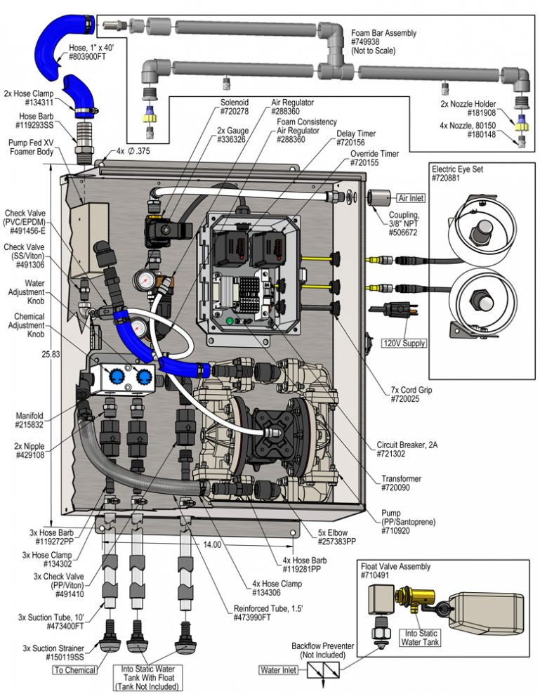
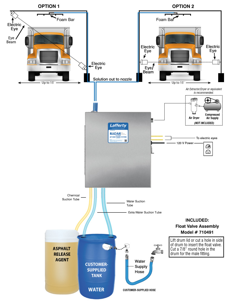
The RADAR™ AP-MM Foam System is an electric eye activated foam applicator that mounts to a user-supplied drive-though arch for applying asphalt release chemicals to truck beds. It is designed for facilities with low or fluctuating water pressure. This system uses compressed air to drive a rugged Sandpiper air-operated, double-diaphragm pump which draws chemical concentrate and water from separate static tanks and blends them "on-the-fly" to create an accurately diluted solution. Rich, clinging foam is created by injecting compressed air into the solution to greatly expand volume and coverage ability. When a truck breaks the electric eye's line-of-sight, a delay timer allows the driver to position the truck under the foam bar before foaming begins and a run timer applies release agent for a pre-set time or until the vehicle leaves the foaming area, whichever is first.

Safety & Operational Precautions

  • See Additional Safety Precautions included with the Electrical Control Box Installation Information
  • Always consider electrical shock hazard when working with and handling electrical equipment. If uncertain, consult an Electrician. Electrical wiring should only be done by a qualified Electrician, per Local and State Electrical Codes.
  • For proper performance do NOT modify, substitute nozzle, hose diameter or length
  • Manufacturer assumes no liability for the use or misuse of this unit.
  • Wear protective clothing, gloves and eye-wear when working with chemicals.
  • Always direct the discharge away from people and electrical devices.
  • Follow the chemical manufacturer’s safe handling instructions.
  • DO NOT use d-Limonene or other chemicals that are not compatible with the Santoprene diaphragms.
  • TEFLON upgrade is available.

To Install (refer to diagram on next page)

  1. Mount the unit to a solid, secure surface. Mount above chemical and water containers.
  2. Do NOT connect to electricity yet.
  3. Choose between Option 1 or 2 as shown in the illustration on page 1. Construct the mounting pole or arch, then mount the electric eyes and foam bar assembly. 
  4. Position the electric eyes so that they are pointed toward each other, creating a "beam.” (You may want to use a string to "line up” the eyes.) The electric eye housing brackets have pre-drilled holes for angled mounting against level surfaces.
    • The Receiver should never be aimed at the sun and should therefore be mounted pointing down, if mounting Option 1 is chosen.
    • Both the Receiver and the Emitter have a red LED. When they are aligned only the Emitter red light is lit. When they are out of alignment both the Emitter and Receiver red lights are lit.
  5. Wire tie the cords securely to the arch.
  6. Install the supplied float valve assembly into your water tank as shown in the illustration on page 3. Attach your water supply hose to the float valve and turn on the water to fill the tank.
  7. Measure and cut the 1/2" suction tube into two sections of suitable length and connect them to the hose barbs as shown in the diagram on next page. One is for chemical concentrate, the other for extra water, if needed.
  8. Connect the 3/4" water suction tube to the hose barb. Secure all tubes with the clamps – do not over-tighten. 
  9. Connect your clean, dry compressed air supply to the system as shown in the illustration. (Air Extractor / Dryer is recommended.)
  10. Make sure the system is not plugged in to a power source. Remove control box cover. The box contains two timers (Delay & Override).
    Delay Timer: This timer allows you to set the time to the approximate number of seconds needed from the time the truck breaks the "beam” of the electric eyes until the truck bed is positioned underneath the foam bar assembly. Set the timer by pushing the combination of dip switches that will equal the total number of seconds you need for the delay.
    Override Timer: This timer controls the maximum amount of time the foamer will operate for. Set the timer by pushing the combination of dip switches that equal the total number of seconds you need the system to foam. Note: if the truck exits before this time has elapsed and the electric eye beam is restored, the foam will stop.
  11. Replace the control box cover.
  12. Plug the power cord into a 120 VAC power outlet. Activate your air supply.
SWITCH SETTINGS (on front of Control Box)
  • ON – Top of switch is depressed. Green light glows. Electric Eyes and timers are bypassed.
  • OFF – Switch is in middle position; green/red lights are off
  • Automatic control – Bottom of switch is depressed. Red light glows. Electric Eyes and timers are in control
TO TEST
  1. Perform "test runs" with water only and make any necessary timer adjustments, and any foam bar and electric eye position adjustments. NOTE: Once the electronic beam is restored, the system automatically shuts off. Make sure to position the electric eyes so that any gap between the cab and truck bed does not cause the system to shut off.
  2. After several successful test runs have been made you are ready to set the chemical dilution.
  3. Immerse chemical suction tube into the chemical container.
  • IF a ready to use chemical solution is being used place all three tubes in the solution.
How to Set Your Dilution Ratio:
  1. Use the chemical / water adjustment knobs to control the amounts of chemical and "extra" water that flow through the unit. The adjustment knobs allow you to achieve virtually any dilution ratio and increase the flow rate of the water IF needed. Start out with the additional water knob turned completely clockwise and add extra water if needed.
  2. Turn the adjustment knobs counterclockwise to increase flow or clockwise to decrease flow.
  3. The chemical knob is preset to two full turns counterclockwise this setting is for initial testing.
  4. To adjust the chemical concentration.
    • For a weaker dilution, turn the chemical knob clockwise.
    • For a stronger dilution, turn the chemical knob counterclockwise.

To Operate

  1. The unit has been tested and is ready to operate. The pump air pressure regulator is preset and 60 PSI. This is the optimum pump pressure. The Foam Consistency regulator is preset at 50 PSI. Test "as is" before making any foam consistency adjustments.
  2. Final dilution ratios and air adjustments will now have to be made.
    • To adjust foam consistency, pull out on the regulator knob and turn the the knob clockwise for dryer foam and counterclockwise for wetter foam.
    • Wait several seconds after each adjustment to see the results.
    • Too much foam consistency air will cause the hose to buck and jump and poor foam quality.
    • If foam remains too wet, slightly turn the chemical adjustment knob counterclockwise to increase chemical concentration or add air.
  3. Once adjustments have been made to timers, chemical dilution and foam consistency, drive the first truck through and make any last adjustments as needed.
  4. The unit is ready for operation.
977930.jpg
Troubleshooting Guide
Problem Possible Cause / Solution
StartupMaintenance
A) Air pump will not run/pump.
B) Foam not acceptable.
C) Unit will not draw chemical.
D) Water tube will not stay primed.
E) Chemical tube will not stay primed.
F) Unit comes on and runs continuously.
G) Asphalt continues to stick to truck.
1, 2, 3, 11, 12
2, 3, 4, 5, 6, 7, 8, 9, 10
5, 6, 7, 8, 9, 10
5, 7
7
11, 12
6, 8
13, 14, 17, 18, 19, 20
13, 14, 15, 16, 19
13, 14, 15, 16, 17, 18, 19, 20, 21
15, 16, 19
15, 16, 19
Possible Cause / Solution
StartupMaintenance
  1. Problem with air pump
    • Refer to pump manual.
  2. Use of an oiler in the airline will cause pump to stall
    • Use only clean, dry air.
  3. Inadequate air supply
    • Adjust air regulator slowly clockwise.
  4. Water knob not adequately opened or open too much
    • Turn water knob counterclockwise/clockwise.
  5. Water tube(s) not immersed in water or water depleted
    • Immerse tube(s) or replenish.
  6. Chemical knob not adequately opened
    • Turn chemical knob counterclockwise.
  7. Chemical tube not immersed in chemical or chemical depleted
    • Immerse tube or replenish.
  8. Improper chemical
    • Ensure product is recommended for the application.
  9. Discharge hose wrong size or kinked (SEE REQUIREMENTS)
  10. Nozzle size too small (SEE REQUIREMENTS)
  11. Timer not be set properly or malfunctioned
    • See Timer Adjustment on page 2 or replace timer.
  12. May have electrical problems
    • Have a qualified electrician check electrical connections. Ensure circuit breaker (5 amp) has not been tripped. 
    • Electric Eyes out of alignment or failed. Realign or replace eyes.
  1. Chemical check valve stuck or failed
    • Clean or replace.
  2. Chemical strainer blocked
    • Clean or replace chemical strainer.
  3. Chemical tube stretched out where tube slides over check valve or pin hole/cut in chemical tube (sucking air in)
    • Cut off end of tube or replace tube.
  4. Vacuum leak in chemical pick-up connections
    • Tighten the connections.
  5. Water check valve stuck or failed
    • Clean or replace.
  6. Water strainers blocked
    • Clean or replace chemical strainers.
  7. Water tubes stretched out where tube slides over check valve or pin hole/cut in water tubes (sucking air in)
    • Cut off end of tube or replace tube.
  8. Air regulator failed allowing too much air or not enough air
    • Clean or replace.
  9. Air solenoid clogged or failed
    • Clean or replace.
PREVENTIVE MAINTENANCE: When the unit will be out of service for extended periods, place chemical tube(s) in water and flush the chemical out of the unit to help prevent chemical from drying out and causing build-up. Periodically check and clean chemical strainer and replace if missing.